element14 Community
element14 Community
    Register Log In
  • Site
  • Search
  • Log In Register
  • About Us
  • Community Hub
    Community Hub
    • What's New on element14
    • Feedback and Support
    • Benefits of Membership
    • Personal Blogs
    • Members Area
    • Achievement Levels
  • Learn
    Learn
    • Ask an Expert
    • eBooks
    • element14 presents
    • Learning Center
    • Tech Spotlight
    • STEM Academy
    • Webinars, Training and Events
    • Learning Groups
  • Technologies
    Technologies
    • 3D Printing
    • FPGA
    • Industrial Automation
    • Internet of Things
    • Power & Energy
    • Sensors
    • Technology Groups
  • Challenges & Projects
    Challenges & Projects
    • Design Challenges
    • element14 presents Projects
    • Project14
    • Arduino Projects
    • Raspberry Pi Projects
    • Project Groups
  • Products
    Products
    • Arduino
    • Avnet Boards Community
    • Dev Tools
    • Manufacturers
    • Multicomp Pro
    • Product Groups
    • Raspberry Pi
    • RoadTests & Reviews
  • Store
    Store
    • Visit Your Store
    • Choose another store...
      • Europe
      •  Austria (German)
      •  Belgium (Dutch, French)
      •  Bulgaria (Bulgarian)
      •  Czech Republic (Czech)
      •  Denmark (Danish)
      •  Estonia (Estonian)
      •  Finland (Finnish)
      •  France (French)
      •  Germany (German)
      •  Hungary (Hungarian)
      •  Ireland
      •  Israel
      •  Italy (Italian)
      •  Latvia (Latvian)
      •  
      •  Lithuania (Lithuanian)
      •  Netherlands (Dutch)
      •  Norway (Norwegian)
      •  Poland (Polish)
      •  Portugal (Portuguese)
      •  Romania (Romanian)
      •  Russia (Russian)
      •  Slovakia (Slovak)
      •  Slovenia (Slovenian)
      •  Spain (Spanish)
      •  Sweden (Swedish)
      •  Switzerland(German, French)
      •  Turkey (Turkish)
      •  United Kingdom
      • Asia Pacific
      •  Australia
      •  China
      •  Hong Kong
      •  India
      •  Korea (Korean)
      •  Malaysia
      •  New Zealand
      •  Philippines
      •  Singapore
      •  Taiwan
      •  Thailand (Thai)
      • Americas
      •  Brazil (Portuguese)
      •  Canada
      •  Mexico (Spanish)
      •  United States
      Can't find the country/region you're looking for? Visit our export site or find a local distributor.
  • Translate
  • Profile
  • Settings
BeagleBoard
  • Products
  • Dev Tools
  • Single-Board Computers
  • BeagleBoard
  • More
  • Cancel
BeagleBoard
Blog Test CAN BUS on BeagleBone
  • Blog
  • Forum
  • Documents
  • Quiz
  • Polls
  • Files
  • Members
  • Mentions
  • Sub-Groups
  • Tags
  • More
  • Cancel
  • New
Join BeagleBoard to participate - click to join for free!
  • Share
  • More
  • Cancel
Group Actions
  • Group RSS
  • More
  • Cancel
Engagement
  • Author Author: Jan Cumps
  • Date Created: 29 Sep 2019 11:59 AM Date Created
  • Views 8877 views
  • Likes 6 likes
  • Comments 6 comments
  • can_bus
  • bbb
  • BeagleBone
  • automotive
  • can
Related
Recommended

Test CAN BUS on BeagleBone

Jan Cumps
Jan Cumps
29 Sep 2019

I'm testing the CAN peripheral on a BeagleBone.

I'll be using my homemade generic CAN driver to implement the physical layer and Thomas Wedemeyer's BB specific instructions.

The other device on the CAN BUS, playing the communication partner role, is a Microchip CAN BUS Analyser.


image

Like most microcontrollers that have a CAN peripheral on board, the Sitara on the BeagleBone doesn't have a physical bus driver.

That's something that needs to be implemented separately.

The CAN driver breakout board I made for an e14 roadtest uses a TCAN332DTCAN332D driver IC.

The CAN Bus analyser from Microchip uses their own MCP2551MCP2551 (this family is used in several Arduino shields).

Check Thomas' blog to see how the driver connects to the BeagleBone.


Test the CAN Bus


Take care that everything is wired up before starting the exercise. The driver has to be connected to the BeagleBone and to a functional CAN bus.

If your device isn't connected to a bus, not a lot will happen physically.

My "functional CAN Bus" is a single Microchip CAN Bus analyser. But any physically correct circuit will work, as long as the voltage levels are compatible with the CAN driver you use.

On a BB Black or Green,  the controller side CAN Rx is on P9.24  and CAN Tx on P9.26.


Once everything is wired, there are 3 activities:


1. Set the BeagleBone pins to CAN function

There are several ways to do that permanently. Thomas' article is very good, check there.

For this exercise, I chose to assign them to CAN function temporary, with the config-pin utility.


sudo config-pin p9.24 can
sudo config-pin p9.26 can


2. Enable the Linux interface

CAN is implemented as a network in Linux. You use similar utilities as when defining a TCP/IP network.


sudo ip link set can1 up type can bitrate 125000
sudo ifconfig can1 up


Again, Thomas' instructions describe a way to do this permanently.


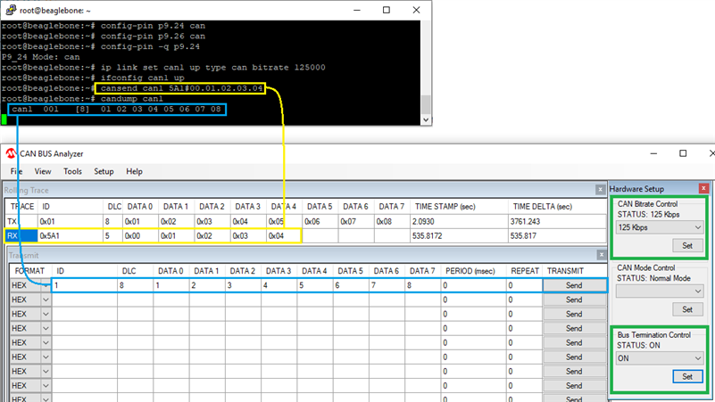
3. Send and Receive Data

The BeagleBone has Linux CAN utilities installed by default these days.

These can be used to try out the CAN network from the BB side. Both for sending and receiving traffic.

You'll need to have something on the bus to play the other role. In this case I used the Microchip analyser. An Arduino MKR with a MKR CAN shield and example sketches works equally well.


cansend can1 5A1#00.01.02.03.04
candump can1


image


The Logic and Physical Layer Signals


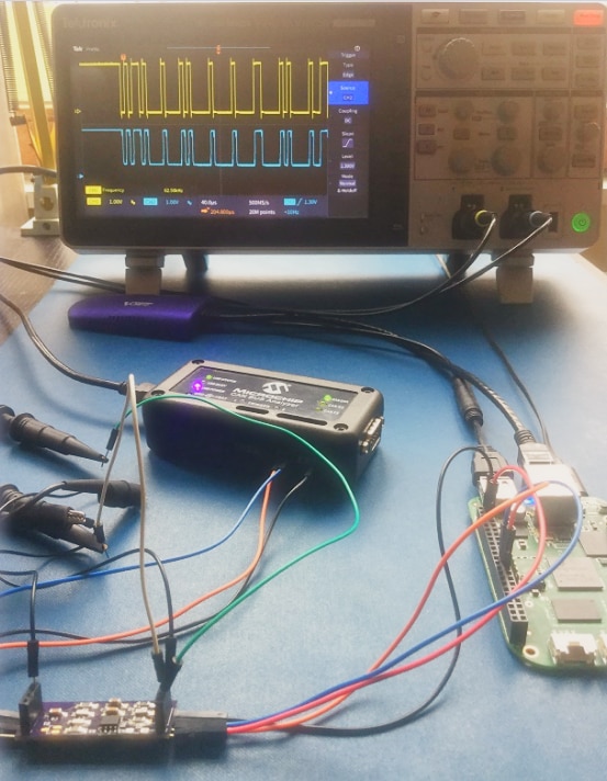
While doing this exercise, I captured some data on both sides of the BB driver.

The logic level has TX and RX signals separate. Both 3.3V logic signals. The physical layer is differential.


CAN data: logic layer - Tx and Rx lineCAN data: physical layer - differential CAN signal
imageimage


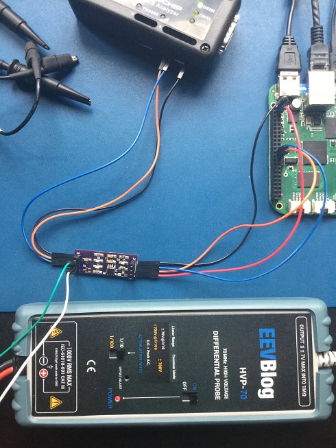
I probed the HI and LO with a differential probe.

image


Related blog
AVNET SmartEdge IIOT Gateway: Use the Isolated CAN
  • Sign in to reply

Top Comments

  • mp2100
    mp2100 over 5 years ago +4
    Thank you Jan Cumps , and apparently Thomas Wedemeyer! I was curious about CAN, so I read this item. But more important for me, I had not come across the config-pin command. I was recently trying to get…
  • Jan Cumps
    Jan Cumps over 4 years ago in reply to mp2100

    I can play along, I have a the CAN add-on for Arduino too (I won it here on element14):

    image

    • Cancel
    • Vote Up 0 Vote Down
    • Sign in to reply
    • More
    • Cancel
  • mp2100
    mp2100 over 4 years ago in reply to Jan Cumps

    I'm glad you sent this update.  I picked up the BBB "Comms Cape" and will be trying to get it to talk.

    https://github.com/beagleboard/capes/tree/master/beaglebone/Comms

    It has CAN included with the transceiver chip.


    My initial attempt was to talk to an arduino UNO with an arduino CAN cape, and didn't get very far.  Stumbling through this soon.

    • Cancel
    • Vote Up 0 Vote Down
    • Sign in to reply
    • More
    • Cancel
  • Jan Cumps
    Jan Cumps over 4 years ago

    I've tested this with in combination with an AVNET SmartEdge (essentially a Raspberry Pi with added hardware), and that works fine.

    image

    Setup of the Smartedge is simpler - the image is prepared , you need to uncomment settings and you have a working  CAN.

    Other differences: the CAN logic is a separate I2C IC there, while on BB it's embedded in the ARM processor.

    Smartedge's bus driver is isolated. My little driver PCB isn't (my choise, not an omission in the BB).


    AVNET SmartEdge IIOT Gateway: Use the Isolated CAN

    • Cancel
    • Vote Up 0 Vote Down
    • Sign in to reply
    • More
    • Cancel
  • mp2100
    mp2100 over 5 years ago

    Thank you Jan Cumps, and apparently Thomas Wedemeyer!  I was curious about CAN, so I read this item.  But more important for me, I had not come across the config-pin command.  I was recently trying to get my BBBlack talking with the UART to my PLC which only has RS232 communication (it's from the 1990s).   I have Derek Molloy's book, I have google searches, but I had not gotten the UART working.  I see your "sudo config-pin p9.24 can" and change it to "sudo config-pin p9.24 uart" and suddenly I am talking to my PLC!  Thanks.

    image

    • Cancel
    • Vote Up +4 Vote Down
    • Sign in to reply
    • More
    • Cancel
  • Jan Cumps
    Jan Cumps over 5 years ago in reply to clem57

    The differential signal is the CAN physical signals that you'll find on any CAN bus. It's part of the standard.

    https://en.wikipedia.org/wiki/CAN_bus#Physical

    The wikipedia article explains it good, including what the role of the differential concept is in this standard.

    • Cancel
    • Vote Up 0 Vote Down
    • Sign in to reply
    • More
    • Cancel
>
element14 Community

element14 is the first online community specifically for engineers. Connect with your peers and get expert answers to your questions.

  • Members
  • Learn
  • Technologies
  • Challenges & Projects
  • Products
  • Store
  • About Us
  • Feedback & Support
  • FAQs
  • Terms of Use
  • Privacy Policy
  • Legal and Copyright Notices
  • Sitemap
  • Cookies

An Avnet Company © 2025 Premier Farnell Limited. All Rights Reserved.

Premier Farnell Ltd, registered in England and Wales (no 00876412), registered office: Farnell House, Forge Lane, Leeds LS12 2NE.

ICP 备案号 10220084.

Follow element14

  • X
  • Facebook
  • linkedin
  • YouTube