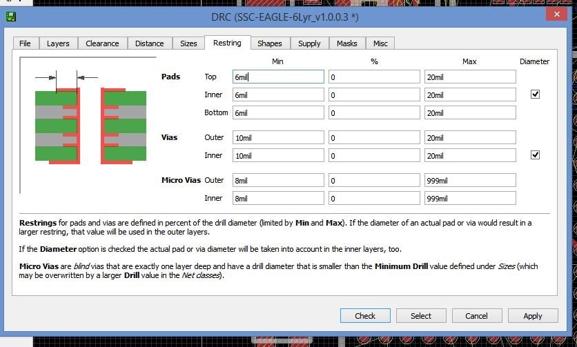
I am currently routing a project and have run into an issue. I have set my drill hole to 6 mil and diameter to 10 mil as well as adjust the restring to 10 mil 0% inner and outer. However, once the via is created it creats as an inner and outer diameter of 26 mil. How do I stop this from happening? This hinders my project as it prevents me from routing the BGA chip.
Thanks,
Blake