element14 Community
element14 Community
    Register Log In
  • Site
  • Search
  • Log In Register
  • Community Hub
    Community Hub
    • What's New on element14
    • Feedback and Support
    • Benefits of Membership
    • Personal Blogs
    • Members Area
    • Achievement Levels
  • Learn
    Learn
    • Ask an Expert
    • eBooks
    • element14 presents
    • Learning Center
    • Tech Spotlight
    • STEM Academy
    • Webinars, Training and Events
    • Learning Groups
  • Technologies
    Technologies
    • 3D Printing
    • FPGA
    • Industrial Automation
    • Internet of Things
    • Power & Energy
    • Sensors
    • Technology Groups
  • Challenges & Projects
    Challenges & Projects
    • Design Challenges
    • element14 presents Projects
    • Project14
    • Arduino Projects
    • Raspberry Pi Projects
    • Project Groups
  • Products
    Products
    • Arduino
    • Avnet & Tria Boards Community
    • Dev Tools
    • Manufacturers
    • Multicomp Pro
    • Product Groups
    • Raspberry Pi
    • RoadTests & Reviews
  • About Us
    About the element14 Community
  • Store
    Store
    • Visit Your Store
    • Choose another store...
      • Europe
      •  Austria (German)
      •  Belgium (Dutch, French)
      •  Bulgaria (Bulgarian)
      •  Czech Republic (Czech)
      •  Denmark (Danish)
      •  Estonia (Estonian)
      •  Finland (Finnish)
      •  France (French)
      •  Germany (German)
      •  Hungary (Hungarian)
      •  Ireland
      •  Israel
      •  Italy (Italian)
      •  Latvia (Latvian)
      •  
      •  Lithuania (Lithuanian)
      •  Netherlands (Dutch)
      •  Norway (Norwegian)
      •  Poland (Polish)
      •  Portugal (Portuguese)
      •  Romania (Romanian)
      •  Russia (Russian)
      •  Slovakia (Slovak)
      •  Slovenia (Slovenian)
      •  Spain (Spanish)
      •  Sweden (Swedish)
      •  Switzerland(German, French)
      •  Turkey (Turkish)
      •  United Kingdom
      • Asia Pacific
      •  Australia
      •  China
      •  Hong Kong
      •  India
      •  Japan
      •  Korea (Korean)
      •  Malaysia
      •  New Zealand
      •  Philippines
      •  Singapore
      •  Taiwan
      •  Thailand (Thai)
      •  Vietnam
      • Americas
      •  Brazil (Portuguese)
      •  Canada
      •  Mexico (Spanish)
      •  United States
      Can't find the country/region you're looking for? Visit our export site or find a local distributor.
  • Translate
  • Profile
  • Settings
Autodesk EAGLE
  • Products
  • More
Autodesk EAGLE
EAGLE User Support (English) GND pads not connecting to GND polygon?
  • Blog
  • Forum
  • Documents
  • Events
  • Polls
  • Files
  • Members
  • Mentions
  • Sub-Groups
  • Tags
  • More
  • Cancel
  • New
Join Autodesk EAGLE to participate - click to join for free!
Actions
  • Share
  • More
  • Cancel
Forum Thread Details
  • State Verified Answer
  • Replies 9 replies
  • Subscribers 188 subscribers
  • Views 2185 views
  • Users 0 members are here
  • plans
  • polygons
  • gnd
Related

GND pads not connecting to GND polygon?

mastermatic
mastermatic over 10 years ago

Hi, I'm trying to create a 4 layer PCB (TOP + POWER + GND + BOTTOM). I created 2 planes for the VBB and GNDBB using polygons.

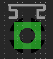
My problem is the connection (let's say) beetween a resistor and the PAD of a component (let's call it X component). If try to connect the VBB connection of the resistor to a Via (and the via's name is VBB) the VBB PAD of the X component with appear like the pic below and the airwire that was connecting the resistor to the X component is gone!
image

But if I try to do the same with a resistor that is connected to a GND pad, the pad stays the same and the airwire is still there, which makes me wonder if the vias are even connecting to the GND plan.


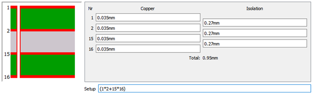
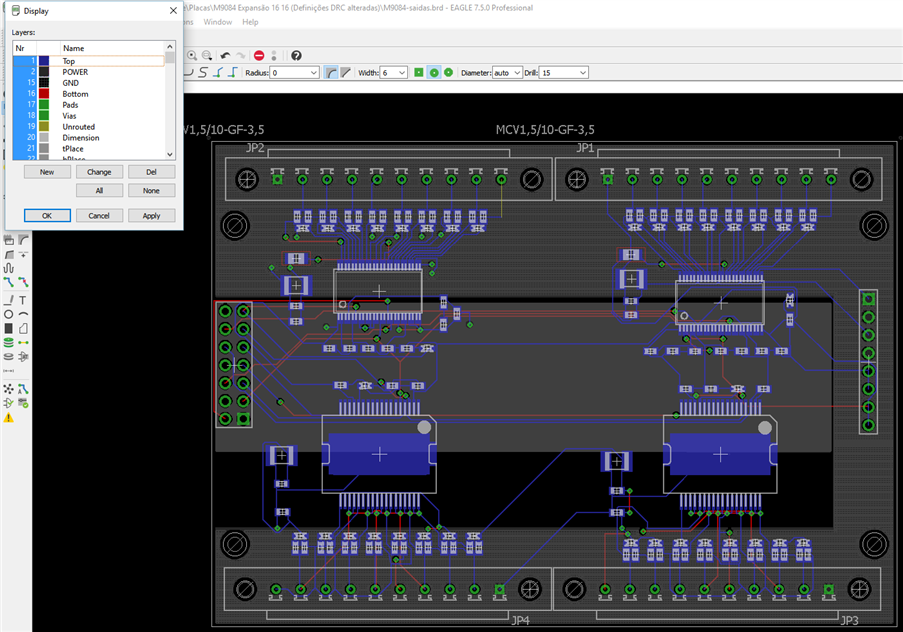
The following are printscreens of the settings I'm currently using.
image

image


What am I doing wrong here?

Any help would be highly appreciated!

  • Sign in to reply
  • Cancel
Parents
  • autodeskguest
    0 autodeskguest over 10 years ago

    On 31.05.2016 13:11, Nuno Gomes wrote:

    Hi, I'm trying to create a 4 layer PCB (TOP + POWER + GND + BOTTOM). I created 2 planes for the VBB and GNDBB using polygons.

    My problem is the connection (let's say) beetween a resistor and the PAD of a component (let's call it X component). If try to connect the VBB connection of the resistor to a Via (and the via's name is VBB) the VBB PAD of the X component with appear like the pic below and the airwire that was connecting the resistor to the X component is gone!

    But if I try to do the same with a resistor that is connected to a GND pad, the pad stays the same and the airwire is still there, which makes me wonder if the vias are even connecting to the GND plan.


    The following are printscreens of the settings I'm currently using.
     

    What am I doing wrong here?

    Any help would be highly appreciated!


    I'm not sure I understand the question.


    Just make sure the through hole GND pad is surrounded by a polygon named

    GND. A SMD resistor pad needs a via closeby to get to inner layer.

    And remember to do ratsnest.


    • Cancel
    • Vote Up 0 Vote Down
    • Sign in to reply
    • Verify Answer
    • Cancel
Reply
  • autodeskguest
    0 autodeskguest over 10 years ago

    On 31.05.2016 13:11, Nuno Gomes wrote:

    Hi, I'm trying to create a 4 layer PCB (TOP + POWER + GND + BOTTOM). I created 2 planes for the VBB and GNDBB using polygons.

    My problem is the connection (let's say) beetween a resistor and the PAD of a component (let's call it X component). If try to connect the VBB connection of the resistor to a Via (and the via's name is VBB) the VBB PAD of the X component with appear like the pic below and the airwire that was connecting the resistor to the X component is gone!

    But if I try to do the same with a resistor that is connected to a GND pad, the pad stays the same and the airwire is still there, which makes me wonder if the vias are even connecting to the GND plan.


    The following are printscreens of the settings I'm currently using.


    What am I doing wrong here?

    Any help would be highly appreciated!


    I'm not sure I understand the question.


    Just make sure the through hole GND pad is surrounded by a polygon named

    GND. A SMD resistor pad needs a via closeby to get to inner layer.

    And remember to do ratsnest.


    • Cancel
    • Vote Up 0 Vote Down
    • Sign in to reply
    • Verify Answer
    • Cancel
Children
  • mastermatic
    0 mastermatic over 10 years ago in reply to autodeskguest

    So, the GND pad on the X component? Like JP2 component on the last picture?

    • Cancel
    • Vote Up 0 Vote Down
    • Sign in to reply
    • Verify Answer
    • Cancel
element14 Community

element14 is the first online community specifically for engineers. Connect with your peers and get expert answers to your questions.

  • Members
  • Learn
  • Technologies
  • Challenges & Projects
  • Products
  • Store
  • About Us
  • Feedback & Support
  • FAQs
  • Terms of Use
  • Privacy Policy
  • Legal and Copyright Notices
  • Sitemap
  • Cookies

An Avnet Company © 2026 Premier Farnell Limited. All Rights Reserved.

Premier Farnell Ltd, registered in England and Wales (no 00876412), registered office: Farnell House, Forge Lane, Leeds LS12 2NE.

Follow element14

  • X
  • Facebook
  • linkedin
  • YouTube