


Hello,
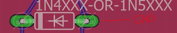
I need to attach the 'Source' on the this diode to GND without changing its name but Eagle will not allow me to do so. I've found older threads that mention creating a 'short' type part to do this.
But, I am wondering if this is made easier with newer version of Eagle? I'm a maker who has managed to create 2 PCB with Eagle that actually work, but still consider myself an extreme newbie.
Any guidance would be greatly appreciated.
Dave

