element14 Community
element14 Community
    Register Log In
  • Site
  • Search
  • Log In Register
  • Community Hub
    Community Hub
    • What's New on element14
    • Feedback and Support
    • Benefits of Membership
    • Personal Blogs
    • Members Area
    • Achievement Levels
  • Learn
    Learn
    • Ask an Expert
    • eBooks
    • element14 presents
    • Learning Center
    • Tech Spotlight
    • STEM Academy
    • Webinars, Training and Events
    • Learning Groups
  • Technologies
    Technologies
    • 3D Printing
    • FPGA
    • Industrial Automation
    • Internet of Things
    • Power & Energy
    • Sensors
    • Technology Groups
  • Challenges & Projects
    Challenges & Projects
    • Design Challenges
    • element14 presents Projects
    • Project14
    • Arduino Projects
    • Raspberry Pi Projects
    • Project Groups
  • Products
    Products
    • Arduino
    • Avnet & Tria Boards Community
    • Dev Tools
    • Manufacturers
    • Multicomp Pro
    • Product Groups
    • Raspberry Pi
    • RoadTests & Reviews
  • About Us
    About the element14 Community
  • Store
    Store
    • Visit Your Store
    • Choose another store...
      • Europe
      •  Austria (German)
      •  Belgium (Dutch, French)
      •  Bulgaria (Bulgarian)
      •  Czech Republic (Czech)
      •  Denmark (Danish)
      •  Estonia (Estonian)
      •  Finland (Finnish)
      •  France (French)
      •  Germany (German)
      •  Hungary (Hungarian)
      •  Ireland
      •  Israel
      •  Italy (Italian)
      •  Latvia (Latvian)
      •  
      •  Lithuania (Lithuanian)
      •  Netherlands (Dutch)
      •  Norway (Norwegian)
      •  Poland (Polish)
      •  Portugal (Portuguese)
      •  Romania (Romanian)
      •  Russia (Russian)
      •  Slovakia (Slovak)
      •  Slovenia (Slovenian)
      •  Spain (Spanish)
      •  Sweden (Swedish)
      •  Switzerland(German, French)
      •  Turkey (Turkish)
      •  United Kingdom
      • Asia Pacific
      •  Australia
      •  China
      •  Hong Kong
      •  India
      •  Japan
      •  Korea (Korean)
      •  Malaysia
      •  New Zealand
      •  Philippines
      •  Singapore
      •  Taiwan
      •  Thailand (Thai)
      •  Vietnam
      • Americas
      •  Brazil (Portuguese)
      •  Canada
      •  Mexico (Spanish)
      •  United States
      Can't find the country/region you're looking for? Visit our export site or find a local distributor.
  • Translate
  • Profile
  • Settings
Autodesk EAGLE
  • Products
  • More
Autodesk EAGLE
EAGLE User Support (English) What is the right width of trace should I choose for 220VAC
  • Blog
  • Forum
  • Documents
  • Events
  • Polls
  • Files
  • Members
  • Mentions
  • Sub-Groups
  • Tags
  • More
  • Cancel
  • New
Join Autodesk EAGLE to participate - click to join for free!
Actions
  • Share
  • More
  • Cancel
Forum Thread Details
  • State Suggested Answer
  • Replies 15 replies
  • Answers 10 answers
  • Subscribers 190 subscribers
  • Views 5714 views
  • Users 0 members are here
  • high voltage
  • trace-width
  • pcb trace
  • eagle 9.0.0
Related

What is the right width of trace should I choose for 220VAC

anthonylauly
anthonylauly over 8 years ago

image

Hi, I want to design a pcb that convert AC (220VAC) to DC (10 V), so I would use a wider trace for the Neutral and Line. First I would like to know what is the measurement unit use in the radius and width toolbox, second what is the difference of the radius and width of the trace, because when I increase the radius, nothing is happen. Third, what is the right number of radius and width for 220 VAC, thank you.

  • Sign in to reply
  • Cancel
Parents
  • rachaelp
    0 rachaelp over 8 years ago

    Hi Anthony,


    I'm going to start by a very strong word of caution. Please be extremely careful when working with mains voltages. If you don't know you can do something safely or are unsure in any way then don't proceed.


    So, that said, you say 10V output but you don't state the current requirements. What are they? What is the power supply type? Is it linear? Is it switching? All these things will affect the current required on the mains input. It's the current requirement which drives the required trace width. On the other hand, the voltage drives the required separation which must be maintained between the live and neutral traces, and also to any other traces, not just the continuous mains voltage but any safety standards which require a particular level of isolation. See the following link for some further explanation: http://www.ni.com/white-paper/2827/en/


    For the clearances specified in IPC-2221 take a look at the following link: http://www.smpspowersupply.com/ipc2221pcbclearance.html

    To calculate the trace widths required take a look at the following link: http://circuitcalculator.com/wordpress/2006/01/31/pcb-trace-width-calculator/


    You don't need to worry about the radius setting in the route tool in EAGLE for now, that's for mitred corners. You can use that to smooth out 45 and 90 degree bends if you wish though.


    Best Regards,


    Rachael

    • Cancel
    • Vote Up +7 Vote Down
    • Sign in to reply
    • Verify Answer
    • Reject Answer
    • Cancel
  • anthonylauly
    0 anthonylauly over 8 years ago in reply to rachaelp

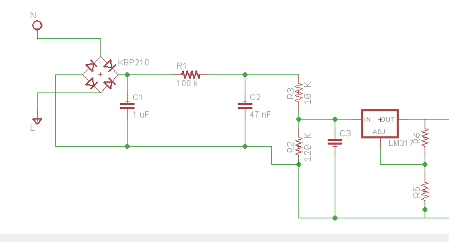
    If I have this kind of circuit  :

    image

    That what is the trace width should I use from the N and L that is connected to the diode bridge ? Because I cannot measure the current flow. The output for the diode bridge is 2 Ampere. Then what is the trace width should I choose ?

    • Cancel
    • Vote Up +2 Vote Down
    • Sign in to reply
    • Verify Answer
    • Reject Answer
    • Cancel
  • jw0752
    0 jw0752 over 8 years ago in reply to anthonylauly

    Hi Anthony,

    You might need to check out the design of your circuit. As drawn the maximum current that it will draw is 2 mA. R1 100K and R3 10K are in series with the regulator. The data sheet on the LM317 indicates that it needs at least 3.5 mA load to maintain regulation and the circuit as drawn can not deliver more than 2 mA and this would be in a default state where the input of the LM317 is shorted to ground. To accomplish what you want to do you will best use a transformer with a 220 volt primary and a 12 volt secondary, then the bridge rectifier and then directly into the input of the LM317 without R1, R2, or R3. C1 and C2 can be combined and should be a lot bigger like 4700 uF if you want to keep ripple down at 2 amps draw. Back to your original question, if 2 amps at 10 volts is being delivered to the load then the 220 volts will be supplying roughly a tenth of an Amp and the traces to the transformer primary will not need to be over sized.

    John

    • Cancel
    • Vote Up +2 Vote Down
    • Sign in to reply
    • Verify Answer
    • Reject Answer
    • Cancel
  • jw0752
    0 jw0752 over 8 years ago in reply to autodeskguest

    Hi Warren,

    Thanks for your good input. FYI these EAGLE questions also show up on the element 14 forum where we routinely answer nuts and bolts questions. Most of the times they are about CAD problems but sometimes, like this one, they demand a response.

    John

    • Cancel
    • Vote Up +4 Vote Down
    • Sign in to reply
    • Verify Answer
    • Reject Answer
    • Cancel
  • autodeskguest
    0 autodeskguest over 8 years ago in reply to anthonylauly

    On 24/06/2018 7:54 p.m., Anthony Lauly wrote:

    Yes sir, all I need is the voltage. theoritically I have considered that calculation though. But sir when I test it on breadboard that the output of the lm317 is connected to attiny85 its alll diferent. I only got around 8 to 12 V DC (I forgot the exact number). And I didn't got till 160 V DC. Do you think something wrong with the addition of attiny because the voltage drop is so big (although it is really helpul).


    Also sir, the calculation of the current, can I directly divide the output voltage of diode bridge with 110K Ohms without considering the 120 K Ohms ?


    --

    To view any images and attachments in this post, visit:

    https://www.element14.com/community/message/241355


    A few thoughts.

    This forum is for suggestions for the Eagle CAD program so this

    discussion is inappropriate here and should be on a basic electronics

    forum elsewhere.


    Your design is bad, dangerous and should not be continued with.


    John showed the input resistors limit the input current to 2.5mA and so

    the LM317 minimum input current needs have not been met and so the LM317

    cannot be expected to function correctly.


    If you read the data sheet for the LM317 you will see it can have a

    maximum of 40volts between input and output. You have subjected it to

    155volts so it may have been damaged. Any output voltage is likely to be

    the result of R5 in parallel with R2. You could confirm this by removing

    the LM317 and metering between  the IN and ADJ pins. I suspect you will

    find very low ohms. The LM317 is robust and contains a lot of protection

    circuitry so you may have been lucky but I would be surprised if it is

    still good.


    There is a technique where you can create a transformerless power supply

    but... it looks simple but requires a great understanding of all the

    factors involved. You may care to read articles on the subject.

    This one below is something to get you started on understanding the

    risks to yourself and the repercussions when components fail.


    https://hackaday.com/2017/04/04/the-shocking-truth-about-transformerless-power-supplies/


    Hope this helps


    Warren


    --

    ... use NNTP://news.cadsoft.de and a functional news reader like

    Thunderbird!


    ---

    This email has been checked for viruses by Avast antivirus software.

    https://www.avast.com/antivirus


    • Cancel
    • Vote Up +4 Vote Down
    • Sign in to reply
    • Verify Answer
    • Reject Answer
    • Cancel
  • Jan Cumps
    0 Jan Cumps over 8 years ago in reply to anthonylauly

    anthonylauly  wrote:


    ...when I test it on breadboard... And I didn't got till 160 V DC...

    Anthony, are you building a mains connected device (in this case not isolated) on a breadboard?

    • Cancel
    • Vote Up +2 Vote Down
    • Sign in to reply
    • Verify Answer
    • Reject Answer
    • Cancel
  • anthonylauly
    0 anthonylauly over 8 years ago in reply to jw0752

    Yes sir, all I need is the voltage. theoritically I have considered that calculation though. But sir when I test it on breadboard that the output of the lm317 is connected to attiny85 its alll diferent. I only got around 8 to 12 V DC (I forgot the exact number). And I didn't got till 160 V DC. Do you think something wrong with the addition of attiny because the voltage drop is so big (although it is really helpul).


    Also sir, the calculation of the current, can I directly divide the output voltage of diode bridge with 110K Ohms without considering the 120 K Ohms ?

    • Cancel
    • Vote Up +1 Vote Down
    • Sign in to reply
    • Verify Answer
    • Cancel
Reply
  • anthonylauly
    0 anthonylauly over 8 years ago in reply to jw0752

    Yes sir, all I need is the voltage. theoritically I have considered that calculation though. But sir when I test it on breadboard that the output of the lm317 is connected to attiny85 its alll diferent. I only got around 8 to 12 V DC (I forgot the exact number). And I didn't got till 160 V DC. Do you think something wrong with the addition of attiny because the voltage drop is so big (although it is really helpul).


    Also sir, the calculation of the current, can I directly divide the output voltage of diode bridge with 110K Ohms without considering the 120 K Ohms ?

    • Cancel
    • Vote Up +1 Vote Down
    • Sign in to reply
    • Verify Answer
    • Cancel
Children
  • jw0752
    0 jw0752 over 8 years ago in reply to autodeskguest

    Hi Warren,

    Thanks for your good input. FYI these EAGLE questions also show up on the element 14 forum where we routinely answer nuts and bolts questions. Most of the times they are about CAD problems but sometimes, like this one, they demand a response.

    John

    • Cancel
    • Vote Up +4 Vote Down
    • Sign in to reply
    • Verify Answer
    • Reject Answer
    • Cancel
  • autodeskguest
    0 autodeskguest over 8 years ago in reply to anthonylauly

    On 24/06/2018 7:54 p.m., Anthony Lauly wrote:

    Yes sir, all I need is the voltage. theoritically I have considered that calculation though. But sir when I test it on breadboard that the output of the lm317 is connected to attiny85 its alll diferent. I only got around 8 to 12 V DC (I forgot the exact number). And I didn't got till 160 V DC. Do you think something wrong with the addition of attiny because the voltage drop is so big (although it is really helpul).


    Also sir, the calculation of the current, can I directly divide the output voltage of diode bridge with 110K Ohms without considering the 120 K Ohms ?


    --

    To view any images and attachments in this post, visit:

    https://www.element14.com/community/message/241355


    A few thoughts.

    This forum is for suggestions for the Eagle CAD program so this

    discussion is inappropriate here and should be on a basic electronics

    forum elsewhere.


    Your design is bad, dangerous and should not be continued with.


    John showed the input resistors limit the input current to 2.5mA and so

    the LM317 minimum input current needs have not been met and so the LM317

    cannot be expected to function correctly.


    If you read the data sheet for the LM317 you will see it can have a

    maximum of 40volts between input and output. You have subjected it to

    155volts so it may have been damaged. Any output voltage is likely to be

    the result of R5 in parallel with R2. You could confirm this by removing

    the LM317 and metering between  the IN and ADJ pins. I suspect you will

    find very low ohms. The LM317 is robust and contains a lot of protection

    circuitry so you may have been lucky but I would be surprised if it is

    still good.


    There is a technique where you can create a transformerless power supply

    but... it looks simple but requires a great understanding of all the

    factors involved. You may care to read articles on the subject.

    This one below is something to get you started on understanding the

    risks to yourself and the repercussions when components fail.


    https://hackaday.com/2017/04/04/the-shocking-truth-about-transformerless-power-supplies/


    Hope this helps


    Warren


    --

    ... use NNTP://news.cadsoft.de and a functional news reader like

    Thunderbird!


    ---

    This email has been checked for viruses by Avast antivirus software.

    https://www.avast.com/antivirus


    • Cancel
    • Vote Up +4 Vote Down
    • Sign in to reply
    • Verify Answer
    • Reject Answer
    • Cancel
  • Jan Cumps
    0 Jan Cumps over 8 years ago in reply to anthonylauly

    anthonylauly  wrote:


    ...when I test it on breadboard... And I didn't got till 160 V DC...

    Anthony, are you building a mains connected device (in this case not isolated) on a breadboard?

    • Cancel
    • Vote Up +2 Vote Down
    • Sign in to reply
    • Verify Answer
    • Reject Answer
    • Cancel
element14 Community

element14 is the first online community specifically for engineers. Connect with your peers and get expert answers to your questions.

  • Members
  • Learn
  • Technologies
  • Challenges & Projects
  • Products
  • Store
  • About Us
  • Feedback & Support
  • FAQs
  • Terms of Use
  • Privacy Policy
  • Legal and Copyright Notices
  • Sitemap
  • Cookies

An Avnet Company © 2026 Premier Farnell Limited. All Rights Reserved.

Premier Farnell Ltd, registered in England and Wales (no 00876412), registered office: Farnell House, Forge Lane, Leeds LS12 2NE.

Follow element14

  • X
  • Facebook
  • linkedin
  • YouTube