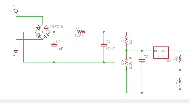
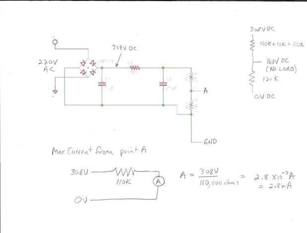
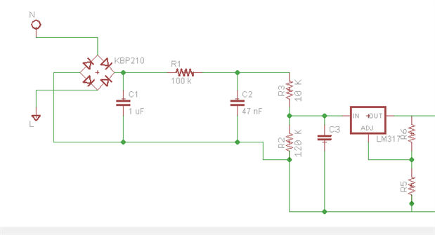
Hi, I want to design a pcb that convert AC (220VAC) to DC (10 V), so I would use a wider trace for the Neutral and Line. First I would like to know what is the measurement unit use in the radius and width toolbox, second what is the difference of the radius and width of the trace, because when I increase the radius, nothing is happen. Third, what is the right number of radius and width for 220 VAC, thank you.