

Hello,
I'm doing my first few boards in Eagle, and so far everything is running perfectly (and will upgrade to the full version now) 
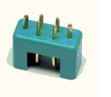
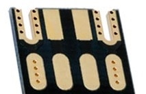
On a new board I'm trying to do I have two 6 pin connectors that I would like to mount on the edge of the board (horisontal). I'm having a hard time how to design that as a footprint. There needs to be to cutouts in the board and these should be plated. I have attached a picture of the connecotor and a picture of how it has been done in another product.
Any help out there ? This is the last thing I need to resolve before my board is being sent (I'm using PCB-POOL)
Thanks for any help (would even consider paying you for a ready made footprint that would do this if reasonable..)

