element14 Community
element14 Community
    Register Log In
  • Site
  • Search
  • Log In Register
  • Community Hub
    Community Hub
    • What's New on element14
    • Feedback and Support
    • Benefits of Membership
    • Personal Blogs
    • Members Area
    • Achievement Levels
  • Learn
    Learn
    • Ask an Expert
    • eBooks
    • element14 presents
    • Learning Center
    • Tech Spotlight
    • STEM Academy
    • Webinars, Training and Events
    • Learning Groups
  • Technologies
    Technologies
    • 3D Printing
    • FPGA
    • Industrial Automation
    • Internet of Things
    • Power & Energy
    • Sensors
    • Technology Groups
  • Challenges & Projects
    Challenges & Projects
    • Design Challenges
    • element14 presents Projects
    • Project14
    • Arduino Projects
    • Raspberry Pi Projects
    • Project Groups
  • Products
    Products
    • Arduino
    • Avnet & Tria Boards Community
    • Dev Tools
    • Manufacturers
    • Multicomp Pro
    • Product Groups
    • Raspberry Pi
    • RoadTests & Reviews
  • About Us
    About the element14 Community
  • Store
    Store
    • Visit Your Store
    • Choose another store...
      • Europe
      •  Austria (German)
      •  Belgium (Dutch, French)
      •  Bulgaria (Bulgarian)
      •  Czech Republic (Czech)
      •  Denmark (Danish)
      •  Estonia (Estonian)
      •  Finland (Finnish)
      •  France (French)
      •  Germany (German)
      •  Hungary (Hungarian)
      •  Ireland
      •  Israel
      •  Italy (Italian)
      •  Latvia (Latvian)
      •  
      •  Lithuania (Lithuanian)
      •  Netherlands (Dutch)
      •  Norway (Norwegian)
      •  Poland (Polish)
      •  Portugal (Portuguese)
      •  Romania (Romanian)
      •  Russia (Russian)
      •  Slovakia (Slovak)
      •  Slovenia (Slovenian)
      •  Spain (Spanish)
      •  Sweden (Swedish)
      •  Switzerland(German, French)
      •  Turkey (Turkish)
      •  United Kingdom
      • Asia Pacific
      •  Australia
      •  China
      •  Hong Kong
      •  India
      •  Japan
      •  Korea (Korean)
      •  Malaysia
      •  New Zealand
      •  Philippines
      •  Singapore
      •  Taiwan
      •  Thailand (Thai)
      •  Vietnam
      • Americas
      •  Brazil (Portuguese)
      •  Canada
      •  Mexico (Spanish)
      •  United States
      Can't find the country/region you're looking for? Visit our export site or find a local distributor.
  • Translate
  • Profile
  • Settings
Autodesk EAGLE
  • Products
  • More
Autodesk EAGLE
Forum Have a question about CadSoft EAGLE?  Ask our Expert, Richard! (Archive)
  • Blog
  • Forum
  • Documents
  • Events
  • Polls
  • Files
  • Members
  • Mentions
  • Sub-Groups
  • Tags
  • More
  • Cancel
  • New
Join Autodesk EAGLE to participate - click to join for free!
Actions
  • Share
  • More
  • Cancel
Forum Thread Details
  • Replies 1129 replies
  • Subscribers 245 subscribers
  • Views 51347 views
  • Users 0 members are here
  • eagle
  • expert
  • richard_hammerl
  • cadsoft
Related

Have a question about CadSoft EAGLE?  Ask our Expert, Richard! (Archive)

nlarson
nlarson over 16 years ago

This thread is now locked - but you can still ask Richard by posting your questions here.  If you'd rather browse other member's questions you can read the CadSoft EAGLE Forums for past questions and answers. Enjoy!


Browse past Q&A help on anything technical relating to CadSoft EAGLE!


image


Richard Hammerl

Richard is an engineer with 16 years experience in EAGLE customer support and is waiting for your questions.

  • Sign in to reply
  • Cancel
  • e14 Contributor
    e14 Contributor over 15 years ago

    Updated Fujitsu MCU libary


    Hi Richard,

    Hope you can help. I want to use the Fujitsu MCU MB96F356RSBPMC1-GSE2MB96F356RSBPMC1-GSE2. But the Fujitsu libary in EAGLE seems to be very old and the new MB96Fxxx devices are not listet. Do you know someone who allready has written a libary element for the MCU above?


    Best regards


    Klaus

    • Cancel
    • Vote Up 0 Vote Down
    • Sign in to reply
    • Cancel
  • e14 Contributor
    e14 Contributor over 15 years ago

    Hi Richard


    Having  problems with 'text menus' in Eagle ver 5.11.0 professional.  I have  setup my eagle.scr file and my eaglerc.usr file to display menus with  icons for some ulp's.  All works fine when eagle is started up and  buttons appear and work.  However, when I switch between different  projects, selecting the board file to open,  I get errors as follows for  all additional text menu items within the eagle.scr file "Unexpected parameter : '[schedule-renum.png] Schedule Renumber : Run renumber-sch.ulp;' and the buttons fail to load for the corresponding schematic window.   If I choose to open a schedule instead then the errors appear for the  corresponding board file.  Have a missed something here, can you shed  any light on this problem as whenever this occurs my eaglerc.usr file  is overwitten without the menus and I have to re-insert them to make it  work again.


    Regards

    Brian.

    • Cancel
    • Vote Up 0 Vote Down
    • Sign in to reply
    • Cancel
  • tubesman
    tubesman over 15 years ago

    I need a Panasonic TS series electrolytic capacitor library. I am looking in Eagle 5.11 and I see the TS parts, but they all have 6 mm lead spacing. I'm not aware of any TS part with a 6 mm lead spacing. They all have 10 mm spacing. This is a real problem for me! Help!  Also, how about the MAX668?

    • Cancel
    • Vote Up 0 Vote Down
    • Sign in to reply
    • Cancel
  • levafreidin
    levafreidin over 15 years ago in reply to flozzi

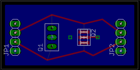
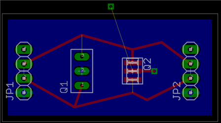
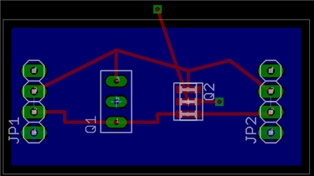
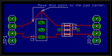
    How to connect two traces to the same pin:


    Picture 1: one GND via has no connection to GND pin

                   (because it is connected to GND polygon):

    image


    Picture 2:  One signal pad and one signal SMD connected.

                    Non-connected GND via moved outside of GND polygon,

                    so after "ratness" command an air wire appears:

    image


    Picture 3: via and pads connected:

    image


    Picture 4: both vias connected:

    image


              Best regards,

                    Lev Freidin.

    • Cancel
    • Vote Up 0 Vote Down
    • Sign in to reply
    • Cancel
  • vicatcu
    vicatcu over 15 years ago in reply to Richard_H

    Richard,


    So in my library, I could just put an SMT pads inside the perimeter of my custom shapes and Eagle will route to those? I imagine I'll get some DRC errors from this "technique" right?


    Victor

    • Cancel
    • Vote Up 0 Vote Down
    • Sign in to reply
    • Cancel
  • Richard_H
    Richard_H over 15 years ago in reply to flozzi

    Hi Michael,


    EAGLE allows 1-2-1 connections with pins and pads only. There is no option to connect one pin with two pads, sorry.

    What you could do is to draw a WIRE in the layout that covers the second pad or the correct way would be to use 4 pins in the symbol and connect each one with a pad.


    Best regards,

    Richard

    • Cancel
    • Vote Up 0 Vote Down
    • Sign in to reply
    • Cancel
  • Richard_H
    Richard_H over 15 years ago in reply to vicatcu

    Hi Victor,


    you have to use a SMD or  a pad as basis for connecting a signal. I am sorry to have to say that there is no possibility to assign a polygon or rect or circle with a signal name in the package editor.

    We will be more flexible there with the next new EAGLE, but this will last a bit.....


    Best regards,
    Richard

    • Cancel
    • Vote Up 0 Vote Down
    • Sign in to reply
    • Cancel
  • flozzi
    flozzi over 15 years ago

    How can I connect X2Ydecoupling capacttors from Johanson wiyh EAGLE? I should connect each pin twice!. If I connect the first pin, the airwire disappears.

    Thanks,

    Michael

    • Cancel
    • Vote Up 0 Vote Down
    • Sign in to reply
    • Cancel
  • vicatcu
    vicatcu over 15 years ago

    Hi Richard,


    I'm creating a custom library part for a layout I'm doing.  The part has some non-standard shaped pads. I have no problem drawing them with a combination of miter and polygon tools in the Pads layer, and putting tStop and bStop "overlays" around them, and put filled polygons into the Milling layer for oblong holes. The problem is that in order to name my custom pads as signals, it seems to me that I have to put a standard (say circular drilled) pad over top of it. It then covers my meticulously measured and decorated custom holes with it's surounding pad. How do I get the effect that I'm going for, which is simply to leave my custom pads alone and name the signals? I've tried setting the rank of my custom Pads to zero and the "standard" pads to seven, but it still looks like the "standard" pad is "on top of" my custom drilled pad...

    • Cancel
    • Vote Up 0 Vote Down
    • Sign in to reply
    • Cancel
  • e14 Contributor
    e14 Contributor over 15 years ago in reply to Richard_H

    Hello,


    Ok. Thank you for your help sir. image


    Tkhan

    • Cancel
    • Vote Up 0 Vote Down
    • Sign in to reply
    • Cancel
<>
element14 Community

element14 is the first online community specifically for engineers. Connect with your peers and get expert answers to your questions.

  • Members
  • Learn
  • Technologies
  • Challenges & Projects
  • Products
  • Store
  • About Us
  • Feedback & Support
  • FAQs
  • Terms of Use
  • Privacy Policy
  • Legal and Copyright Notices
  • Sitemap
  • Cookies

An Avnet Company © 2026 Premier Farnell Limited. All Rights Reserved.

Premier Farnell Ltd, registered in England and Wales (no 00876412), registered office: Farnell House, Forge Lane, Leeds LS12 2NE.

Follow element14

  • X
  • Facebook
  • linkedin
  • YouTube