element14 Community
element14 Community
    Register Log In
  • Site
  • Search
  • Log In Register
  • Community Hub
    Community Hub
    • What's New on element14
    • Feedback and Support
    • Benefits of Membership
    • Personal Blogs
    • Members Area
    • Achievement Levels
  • Learn
    Learn
    • Ask an Expert
    • eBooks
    • element14 presents
    • Learning Center
    • Tech Spotlight
    • STEM Academy
    • Webinars, Training and Events
    • Learning Groups
  • Technologies
    Technologies
    • 3D Printing
    • FPGA
    • Industrial Automation
    • Internet of Things
    • Power & Energy
    • Sensors
    • Technology Groups
  • Challenges & Projects
    Challenges & Projects
    • Design Challenges
    • element14 presents Projects
    • Project14
    • Arduino Projects
    • Raspberry Pi Projects
    • Project Groups
  • Products
    Products
    • Arduino
    • Avnet & Tria Boards Community
    • Dev Tools
    • Manufacturers
    • Multicomp Pro
    • Product Groups
    • Raspberry Pi
    • RoadTests & Reviews
  • About Us
    About the element14 Community
  • Store
    Store
    • Visit Your Store
    • Choose another store...
      • Europe
      •  Austria (German)
      •  Belgium (Dutch, French)
      •  Bulgaria (Bulgarian)
      •  Czech Republic (Czech)
      •  Denmark (Danish)
      •  Estonia (Estonian)
      •  Finland (Finnish)
      •  France (French)
      •  Germany (German)
      •  Hungary (Hungarian)
      •  Ireland
      •  Israel
      •  Italy (Italian)
      •  Latvia (Latvian)
      •  
      •  Lithuania (Lithuanian)
      •  Netherlands (Dutch)
      •  Norway (Norwegian)
      •  Poland (Polish)
      •  Portugal (Portuguese)
      •  Romania (Romanian)
      •  Russia (Russian)
      •  Slovakia (Slovak)
      •  Slovenia (Slovenian)
      •  Spain (Spanish)
      •  Sweden (Swedish)
      •  Switzerland(German, French)
      •  Turkey (Turkish)
      •  United Kingdom
      • Asia Pacific
      •  Australia
      •  China
      •  Hong Kong
      •  India
      •  Japan
      •  Korea (Korean)
      •  Malaysia
      •  New Zealand
      •  Philippines
      •  Singapore
      •  Taiwan
      •  Thailand (Thai)
      •  Vietnam
      • Americas
      •  Brazil (Portuguese)
      •  Canada
      •  Mexico (Spanish)
      •  United States
      Can't find the country/region you're looking for? Visit our export site or find a local distributor.
  • Translate
  • Profile
  • Settings
Autodesk EAGLE
  • Products
  • More
Autodesk EAGLE
Forum Atmega328 - Newbie design
  • Blog
  • Forum
  • Documents
  • Events
  • Polls
  • Files
  • Members
  • Mentions
  • Sub-Groups
  • Tags
  • More
  • Cancel
  • New
Join Autodesk EAGLE to participate - click to join for free!
Actions
  • Share
  • More
  • Cancel
Forum Thread Details
  • State Verified Answer
  • Replies 16 replies
  • Answers 1 answer
  • Subscribers 190 subscribers
  • Views 2029 views
  • Users 0 members are here
Related

Atmega328 - Newbie design

anishkgt
anishkgt over 9 years ago

Hi All,


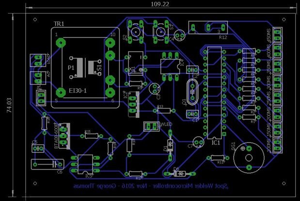
A little new to the Eagle PCB, so please bear with my silly questions. I had designed a single sided board and all ready for etching. Printed the circuit on paper, only to find out that ATmega328 does not fit in the printout. Download all available libraries of eagle and non seem to be working.


Any help would be appreciated.

  • Sign in to reply
  • Cancel
Parents
  • michaelkellett
    0 michaelkellett over 9 years ago

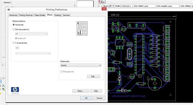
    Are you sure that your printer is printing at exactly 1:1 ratio - check the board overall dimensions to scale the printer.


    MK

    • Cancel
    • Vote Up 0 Vote Down
    • Sign in to reply
    • Verify Answer
    • Cancel
  • anishkgt
    0 anishkgt over 9 years ago in reply to michaelkellett

    All were working earlier. now all of a sudden its happening. I've also re-installed eagle. Below is the dimensions in mmimage

    image

    • Cancel
    • Vote Up 0 Vote Down
    • Sign in to reply
    • Verify Answer
    • Cancel
  • jc2048
    0 jc2048 over 9 years ago in reply to anishkgt

    That's a horrible layout (in my opinion). Did an autorouter do it? If the primary of your transformer has mains on it, you need much better spacing there than the minimum default setting. The ground layout on the secondary side could be much better too. Having the output cap for the regulator up next to the switches at the top seems like an odd placement. You might also want to increase the widths of the tracks (for current handling ability) around the load switch and the snubber components. The isolation figure for the opto device controlling the triac is meaningless if you push tracks from the low voltage side between the pins on the high voltage side.


    If you have to have a single-sided layout, perhaps consider a few wire links on the top rather than the very convoluted paths on the bottom layer.


    Sorry if that sounds like a bit of a brutal critique. It's meant to be helpful (so you can improve the layout) rather than stop you in your tracks (so to speak).

    • Cancel
    • Vote Up +2 Vote Down
    • Sign in to reply
    • Verify Answer
    • Reject Answer
    • Cancel
  • cstanton
    0 cstanton 1 month ago in reply to anishkgt

    Well I'll be.
    Great work!

    • Cancel
    • Vote Up +1 Vote Down
    • Sign in to reply
    • Verify Answer
    • Cancel
  • anishkgt
    0 anishkgt 1 month ago in reply to jc2048

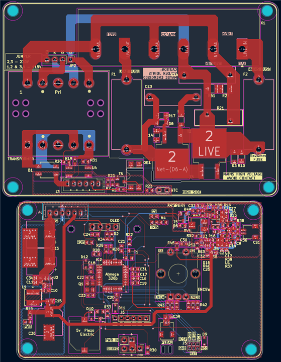
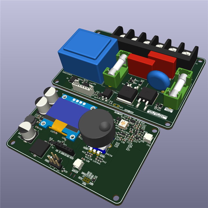
    Just thought i'd share what 10 years turned out to be since i first posted my layout here when i started with PCB design as a hobby.

    Yes I took your critique positive.

    image image

    • Cancel
    • Vote Up +3 Vote Down
    • Sign in to reply
    • Verify Answer
    • Cancel
  • jc2048
    0 jc2048 over 9 years ago in reply to anishkgt

    I thought the devices down the board were selection links. They're LEDs, so of course you need the resistors.


    To carry 5 amps, at 25C, on a board with 1oz copper, with no more than a 10C temperature rise you need a track width of something like 2.8mm (that applies whatever the voltage). However a fuse doesn't blow at the rated current (at least not quickly - look in a datasheet which will have a graph of time-to-blow against current), so you would do well to increase that to cover more than 5A. If you want to see how current varies with track width there are plenty of track width calculators online.


    I can't go any further than this with the mains side. It's not something that I normally do and I'm not qualified to hand out advice as to how it should be done (I know what you shouldn't do, but I'm less clear on what you should do). In particular, I can't advise you on the clearances you need. I know it gets complicated, because it includes making judgements about factors like the environment the board will be in, and being careful to distinguish clearance (the distance through the air between two conductors) and creepage (the distance along a surface between two conductors) which may have different ratings.


    Are you sure you really need to be doing the mains layout? Can you not do what you want to do with a PSU and a solid state relay?

    • Cancel
    • Vote Up 0 Vote Down
    • Sign in to reply
    • Verify Answer
    • Cancel
Reply
  • jc2048
    0 jc2048 over 9 years ago in reply to anishkgt

    I thought the devices down the board were selection links. They're LEDs, so of course you need the resistors.


    To carry 5 amps, at 25C, on a board with 1oz copper, with no more than a 10C temperature rise you need a track width of something like 2.8mm (that applies whatever the voltage). However a fuse doesn't blow at the rated current (at least not quickly - look in a datasheet which will have a graph of time-to-blow against current), so you would do well to increase that to cover more than 5A. If you want to see how current varies with track width there are plenty of track width calculators online.


    I can't go any further than this with the mains side. It's not something that I normally do and I'm not qualified to hand out advice as to how it should be done (I know what you shouldn't do, but I'm less clear on what you should do). In particular, I can't advise you on the clearances you need. I know it gets complicated, because it includes making judgements about factors like the environment the board will be in, and being careful to distinguish clearance (the distance through the air between two conductors) and creepage (the distance along a surface between two conductors) which may have different ratings.


    Are you sure you really need to be doing the mains layout? Can you not do what you want to do with a PSU and a solid state relay?

    • Cancel
    • Vote Up 0 Vote Down
    • Sign in to reply
    • Verify Answer
    • Cancel
Children
No Data
element14 Community

element14 is the first online community specifically for engineers. Connect with your peers and get expert answers to your questions.

  • Members
  • Learn
  • Technologies
  • Challenges & Projects
  • Products
  • Store
  • About Us
  • Feedback & Support
  • FAQs
  • Terms of Use
  • Privacy Policy
  • Legal and Copyright Notices
  • Sitemap
  • Cookies

An Avnet Company © 2026 Premier Farnell Limited. All Rights Reserved.

Premier Farnell Ltd, registered in England and Wales (no 00876412), registered office: Farnell House, Forge Lane, Leeds LS12 2NE.

Follow element14

  • X
  • Facebook
  • linkedin
  • YouTube