element14 Community
element14 Community
    Register Log In
  • Site
  • Search
  • Log In Register
  • Community Hub
    Community Hub
    • What's New on element14
    • Feedback and Support
    • Benefits of Membership
    • Personal Blogs
    • Members Area
    • Achievement Levels
  • Learn
    Learn
    • Ask an Expert
    • eBooks
    • element14 presents
    • Learning Center
    • Tech Spotlight
    • STEM Academy
    • Webinars, Training and Events
    • Learning Groups
  • Technologies
    Technologies
    • 3D Printing
    • FPGA
    • Industrial Automation
    • Internet of Things
    • Power & Energy
    • Sensors
    • Technology Groups
  • Challenges & Projects
    Challenges & Projects
    • Design Challenges
    • element14 presents Projects
    • Project14
    • Arduino Projects
    • Raspberry Pi Projects
    • Project Groups
  • Products
    Products
    • Arduino
    • Avnet & Tria Boards Community
    • Dev Tools
    • Manufacturers
    • Multicomp Pro
    • Product Groups
    • Raspberry Pi
    • RoadTests & Reviews
  • About Us
  • Store
    Store
    • Visit Your Store
    • Choose another store...
      • Europe
      •  Austria (German)
      •  Belgium (Dutch, French)
      •  Bulgaria (Bulgarian)
      •  Czech Republic (Czech)
      •  Denmark (Danish)
      •  Estonia (Estonian)
      •  Finland (Finnish)
      •  France (French)
      •  Germany (German)
      •  Hungary (Hungarian)
      •  Ireland
      •  Israel
      •  Italy (Italian)
      •  Latvia (Latvian)
      •  
      •  Lithuania (Lithuanian)
      •  Netherlands (Dutch)
      •  Norway (Norwegian)
      •  Poland (Polish)
      •  Portugal (Portuguese)
      •  Romania (Romanian)
      •  Russia (Russian)
      •  Slovakia (Slovak)
      •  Slovenia (Slovenian)
      •  Spain (Spanish)
      •  Sweden (Swedish)
      •  Switzerland(German, French)
      •  Turkey (Turkish)
      •  United Kingdom
      • Asia Pacific
      •  Australia
      •  China
      •  Hong Kong
      •  India
      •  Korea (Korean)
      •  Malaysia
      •  New Zealand
      •  Philippines
      •  Singapore
      •  Taiwan
      •  Thailand (Thai)
      • Americas
      •  Brazil (Portuguese)
      •  Canada
      •  Mexico (Spanish)
      •  United States
      Can't find the country/region you're looking for? Visit our export site or find a local distributor.
  • Translate
  • Profile
  • Settings
Autodesk EAGLE
  • Products
  • More
Autodesk EAGLE
Forum bench power supply
  • Blog
  • Forum
  • Documents
  • Events
  • Polls
  • Files
  • Members
  • Mentions
  • Sub-Groups
  • Tags
  • More
  • Cancel
  • New
Join Autodesk EAGLE to participate - click to join for free!
Actions
  • Share
  • More
  • Cancel
Forum Thread Details
  • State Verified Answer
  • Replies 42 replies
  • Answers 20 answers
  • Subscribers 179 subscribers
  • Views 7058 views
  • Users 0 members are here
Related

bench power supply

aster94
aster94 over 8 years ago

hello,


I started drawing in eagle this afternoon to make my first home made pbc board for a bench power supply that with an input of 12V/5A will have two output of 12V, 5V, 3.3V and an adjustable voltage (lm317)

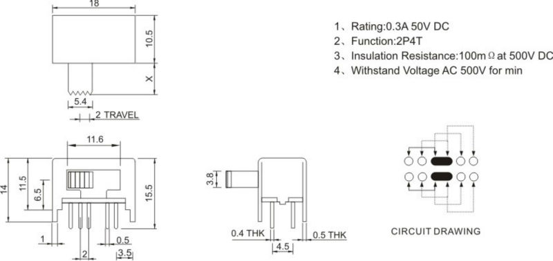
the switches are these with ground in the middle

565935243_150.jpg

I hope that the schematic is clear (it is also in the attachments), maybe you could give me some hint or advice about something that i m doing wrong

about the .brd i didn't route it since maybe you will say me to modify my schematic


thanks in advance


Immagine.png

Attachments:
bps.rar
  • Sign in to reply
  • Cancel

Top Replies

  • COMPACT
    COMPACT over 8 years ago in reply to mcb1 +3 suggested
    Here is an example of what I mean. 8V in from a regulated power supply being output as 5VDC using an LM7805 Linear Regulator. (The current limit has been set to 50mA on the bench power supply as not to…
  • mcb1
    mcb1 over 8 years ago in reply to aster94 +2 suggested
    the rated current it is 0.5 at 50v so I could reach 2A at 12v It doesn't work that way. The current specifies how much the switch will pass without damaging the contacts. The voltage specifies how high…
  • aster94
    aster94 over 8 years ago in reply to mcb1 +2
    As it is clear I am an hobbyist, thanks for the hint about the current In your schematics the middle pin of the potentiometer is not connected, is it correct? Is this schematic also good? http://www.electronics…
Parents
  • aster94
    0 aster94 over 8 years ago

    board redesigned with:

    -added protection diode for 7812

    -removed slider switch

    -added ceramic cap for every IC

    -modified the wiring of the potentiometer


    image


    i hope it is ok image

    • Cancel
    • Vote Up +1 Vote Down
    • Sign in to reply
    • Verify Answer
    • Cancel
  • geralds
    0 geralds over 8 years ago in reply to aster94

    Hi,


    please check the detail with the amp-meter - its something wrong as I seen in the blockdiagram of the meter.


    Best Regards,

    Gerald

    ---

    • Cancel
    • Vote Up 0 Vote Down
    • Sign in to reply
    • Verify Answer
    • Reject Answer
    • Cancel
  • aster94
    0 aster94 over 8 years ago in reply to geralds

    I think i should aliment the ammeter between 4.5 and 30v and i do it (upper part of the shematic)

    For the measurements:

    black wire to VOLTMETER GND

    Red to AMMETER-OUT/VOLTMETER-IN

    blue to AMMETER-IN


    So the lm317 now is correct imageimage??

    • Cancel
    • Vote Up 0 Vote Down
    • Sign in to reply
    • Verify Answer
    • Cancel
  • geralds
    0 geralds over 8 years ago in reply to aster94

    image

    hi,

    please look exactly.

    image

    Gerald

    ---

    • Cancel
    • Vote Up 0 Vote Down
    • Sign in to reply
    • Reject Answer
    • Cancel
  • aster94
    0 aster94 over 8 years ago in reply to geralds

    ok, i think that i get it now and i will also take ideas from your schematic. when i will receive the lm7812 i will make the board (ordered only yesterday)

    • Cancel
    • Vote Up 0 Vote Down
    • Sign in to reply
    • Verify Answer
    • Cancel
Reply
  • aster94
    0 aster94 over 8 years ago in reply to geralds

    ok, i think that i get it now and i will also take ideas from your schematic. when i will receive the lm7812 i will make the board (ordered only yesterday)

    • Cancel
    • Vote Up 0 Vote Down
    • Sign in to reply
    • Verify Answer
    • Cancel
Children
  • geralds
    0 geralds over 8 years ago in reply to aster94

    Hi,

    Attached you'll find the schematic.

    You can use freely all what you needs; its my pleasure.

    Then with this you can build your pcb.

    There is also a heatsink on there you can mount the V-regulators.

    But use for all an isolation pad between the device and heatsink.

    Also isolate all screws.

    After mounting check it with an Ohm (wire finder) -Meter !!!!!!!


    The isolated DC/DC converter is a pcb mounted type like NME1209, or similar. An ISOLATED DC/DC converter is necessary.

    At the output of the DC/DC you have a resistor with 270 Ohm. That can be a higher value <1k (9mA, 9V); >270 (30mA, 9V)

    The thinking about is that the DC/DC needs a load resistance for regulation the output voltage to the nominal value (9V).

    With that R you makes the minimum burden current for this converter;

    see in the datasheet which minimum current it needs and then calculate the resistor value.


    Yes, IC1 is a LM317T.

    The other regulators are LDOs with attribute S - 78S12.... that have a better dropout voltage.

    At the input you find a filter - that filters out spikes from the power supply that you use for this regulators.

    -> You have to see that you use up to > 3A if all regulators are working. -> the filter with min. 6A would be ok.

    The max. input voltage will be 15V because the DC/DC converter can not more stressed.

    Here you have a zener diode ZD15V with 1 Watt. This is for security if the input voltage increase over 15V.

    But stay always under 1 Watt power lost (over voltage and current through the zener).


    I've build the schematic with Eagle V7.7.0.


    I wish you the best for your project.

    Best Regards,

    Gerald

    ---

    Attachments:
    powertripple1.zip
    • Cancel
    • Vote Up +1 Vote Down
    • Sign in to reply
    • Verify Answer
    • Reject Answer
    • Cancel
element14 Community

element14 is the first online community specifically for engineers. Connect with your peers and get expert answers to your questions.

  • Members
  • Learn
  • Technologies
  • Challenges & Projects
  • Products
  • Store
  • About Us
  • Feedback & Support
  • FAQs
  • Terms of Use
  • Privacy Policy
  • Legal and Copyright Notices
  • Sitemap
  • Cookies

An Avnet Company © 2025 Premier Farnell Limited. All Rights Reserved.

Premier Farnell Ltd, registered in England and Wales (no 00876412), registered office: Farnell House, Forge Lane, Leeds LS12 2NE.

ICP 备案号 10220084.

Follow element14

  • X
  • Facebook
  • linkedin
  • YouTube