element14 Community
element14 Community
    Register Log In
  • Site
  • Search
  • Log In Register
  • Community Hub
    Community Hub
    • What's New on element14
    • Feedback and Support
    • Benefits of Membership
    • Personal Blogs
    • Members Area
    • Achievement Levels
  • Learn
    Learn
    • Ask an Expert
    • eBooks
    • element14 presents
    • Learning Center
    • Tech Spotlight
    • STEM Academy
    • Webinars, Training and Events
    • Learning Groups
  • Technologies
    Technologies
    • 3D Printing
    • FPGA
    • Industrial Automation
    • Internet of Things
    • Power & Energy
    • Sensors
    • Technology Groups
  • Challenges & Projects
    Challenges & Projects
    • Design Challenges
    • element14 presents Projects
    • Project14
    • Arduino Projects
    • Raspberry Pi Projects
    • Project Groups
  • Products
    Products
    • Arduino
    • Avnet Boards Community
    • Dev Tools
    • Manufacturers
    • Multicomp Pro
    • Product Groups
    • Raspberry Pi
    • RoadTests & Reviews
  • About Us
  • Store
    Store
    • Visit Your Store
    • Choose another store...
      • Europe
      •  Austria (German)
      •  Belgium (Dutch, French)
      •  Bulgaria (Bulgarian)
      •  Czech Republic (Czech)
      •  Denmark (Danish)
      •  Estonia (Estonian)
      •  Finland (Finnish)
      •  France (French)
      •  Germany (German)
      •  Hungary (Hungarian)
      •  Ireland
      •  Israel
      •  Italy (Italian)
      •  Latvia (Latvian)
      •  
      •  Lithuania (Lithuanian)
      •  Netherlands (Dutch)
      •  Norway (Norwegian)
      •  Poland (Polish)
      •  Portugal (Portuguese)
      •  Romania (Romanian)
      •  Russia (Russian)
      •  Slovakia (Slovak)
      •  Slovenia (Slovenian)
      •  Spain (Spanish)
      •  Sweden (Swedish)
      •  Switzerland(German, French)
      •  Turkey (Turkish)
      •  United Kingdom
      • Asia Pacific
      •  Australia
      •  China
      •  Hong Kong
      •  India
      •  Korea (Korean)
      •  Malaysia
      •  New Zealand
      •  Philippines
      •  Singapore
      •  Taiwan
      •  Thailand (Thai)
      • Americas
      •  Brazil (Portuguese)
      •  Canada
      •  Mexico (Spanish)
      •  United States
      Can't find the country/region you're looking for? Visit our export site or find a local distributor.
  • Translate
  • Profile
  • Settings
Autodesk EAGLE
  • Products
  • More
Autodesk EAGLE
Forum Amega328p-au shorted pins ?
  • Blog
  • Forum
  • Documents
  • Events
  • Polls
  • Files
  • Members
  • Mentions
  • Sub-Groups
  • Tags
  • More
  • Cancel
  • New
Join Autodesk EAGLE to participate - click to join for free!
Actions
  • Share
  • More
  • Cancel
Forum Thread Details
  • State Suggested Answer
  • Replies 47 replies
  • Answers 6 answers
  • Subscribers 179 subscribers
  • Views 5517 views
  • Users 0 members are here
Related

Amega328p-au shorted pins ?

n2nxz
n2nxz over 8 years ago

Finally motivated myself into trying Eagle files only to see my original instincts told me NOT to bother.

The last thing I expected was not finding common components in the library.My first mistake to assume that an Atmega328p-au would be one of the easiest to find.Not so and had to search the ends of the earth to find it and manually place it into the LIBR directory.After a 4 hour search and finally having this IC in my schematic layout I now see"shorts on several pins of this chip in the BRD window.The worse possible places no less on 3.3v and ground

I can probably modify this file but now getting far deeper into a simple project I thought would be straight forward.

Is it a software glitch causing this or a bad library file ?

Anyone know where to find a working Atmega328p-au footprint

See attached screen shot of the issue.

image

  • Sign in to reply
  • Cancel

Top Replies

  • n2nxz
    n2nxz over 6 years ago in reply to n2nxz +3 suggested
    Been some time and have made great progress with help from this group. Thanks to Rachel and others for your patience and help. I have since taken a long break from these circuits but had a lot of fun and…
  • n2nxz
    n2nxz over 8 years ago in reply to rachaelp +2
    Rachel, Thank you for the positive feed back. Still working on some boards sent to me by a friend that are much better design.But hope to revise my own again soon. I made an attempt last week to launch…
  • n2nxz
    n2nxz over 7 years ago in reply to n2nxz +2 suggested
    Just for FYI,a website was started with details of this circuit and hobby - radio-signals forum – radio-signals.com Jim
  • rachaelp
    0 rachaelp over 8 years ago in reply to n2nxz

    Hi James,


    I think it's probably ok. If you place the crystal where you want it, near the IC pins and then the caps the other side where you want them, if you then press the ratsnest button or type RAT <return> you should see it re-optimise the air wires to the order you expect.


    The other thing to note is in the image of the schematic above it is warning about forward and back annotation being severed. You need to make sure you always have both the schematic and board open and never make any changes that will affect the netlist when one or the other is closed otherwise you will end up in a mess.


    Best Regards,


    Rachael

    • Cancel
    • Vote Up 0 Vote Down
    • Sign in to reply
    • Verify Answer
    • Cancel
  • n2nxz
    0 n2nxz over 8 years ago in reply to rachaelp

    Thank you for the note.

    Still need to learn about the options the program has yet plus need to orient my head to seeing a circuit rather than a diagram.

    This has been a big transition to me since my projects were mostly been accomplished using diagrams rather than schematics.

    I`ll get used to this yet.

    Appreciate the help once again.I need to adjust my eyes and look this over a bit closer.

    Auto routing helped a lot so far rather than a spaghetti of lines image

    Also,being very careful when checking from schem to board not to change anything to goof it all up.

    • Cancel
    • Vote Up 0 Vote Down
    • Sign in to reply
    • Verify Answer
    • Cancel
  • n2nxz
    0 n2nxz over 8 years ago in reply to n2nxz

    After several days and many hours I am giving up on Eagle.

    My project is too simple and struggling with this software is making it much harder than it should be.

    This has been tried on 3 machines to eliminate OS as the cause.Searched high and low for footprints and symbols for my specific components.

    Read every forum post and video and nothing works like is said or seen.

    In the end,I took 3 simple components which were a pair of identical 5 pin headers and a 10 pin IC (Si5351a) and simply connected the pins to just that all by itself.

    I get nothing but errors all day long.

    Just downloaded the complete Adafruit Si5351a ,BRD/SCHEM and ran it into Eagle using all and every method learned from videos and forums and still it shows the same errors.

    I changed drills,mils and mm`s and other settings and sizes with no results...not even slight changes.

    Since my project is not protecting the universe,going to mount these tiny components onto thin light material using glue and soldering point to point.

    The time spent on software and computers was time spent soldering image

    Thanks for the help but time to move forward.

    • Cancel
    • Vote Up 0 Vote Down
    • Sign in to reply
    • Verify Answer
    • Cancel
  • n2nxz
    0 n2nxz over 8 years ago in reply to n2nxz

    I think someone needs to try the Si5351a synthesizer chip first and could be Eagle free version is incapable of using it?

    • Cancel
    • Vote Up 0 Vote Down
    • Sign in to reply
    • Verify Answer
    • Cancel
  • rachaelp
    0 rachaelp over 8 years ago in reply to n2nxz

    Hi James,


    Can you post up a sample of the errors you are seeing here please so we can see what's happening?


    Also, can you attach the .lbr file you found containing the Si5351a and I will take a look at it.


    Best Regards,


    Rachael

    • Cancel
    • Vote Up 0 Vote Down
    • Sign in to reply
    • Verify Answer
    • Cancel
  • n2nxz
    0 n2nxz over 8 years ago in reply to rachaelp

    I think this is what I have been using - https://www.snapeda.com/parts/SI5351A-B-GT/Silicon%20Labs/view-part/

    Also,tried using this schematic and get the very same clearance issues with the Si5351a.

    https://github.com/adafruit/Adafruit-Si5351A-Clock-Generator-Breakout-PCB

    I even tried to route my own but can not seem to make the traces small enough.They end up touching.But even using the plain Si5351a chip on a pair of 5 pin headers the clearance error continues.

    I just can not seem to fix this error.

    Had the entire schematic made and remade several times and getting tired.Tried the board portion equally as much and everything in between.

    Following the video steps exactly and getting different results.

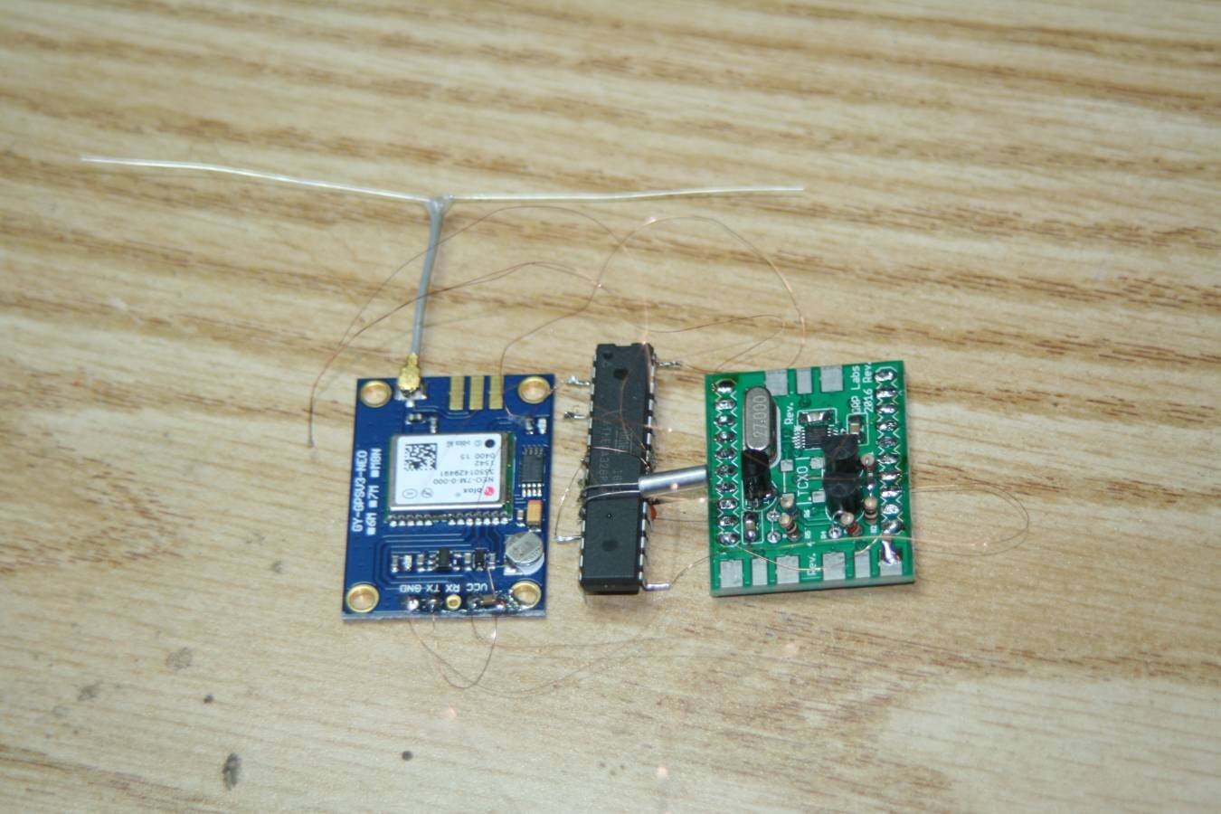
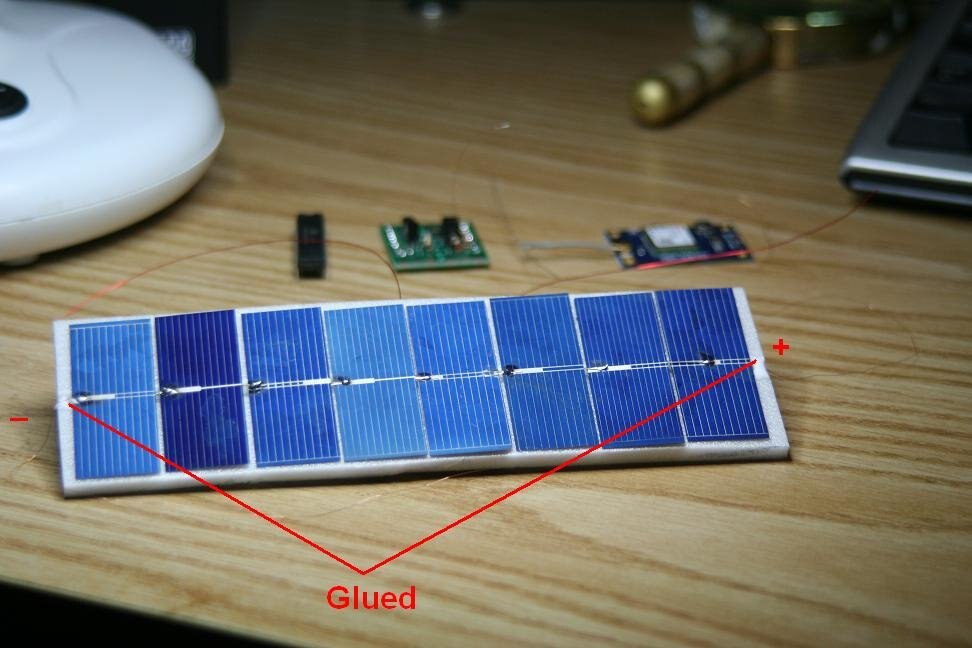
    I should describe this circuit.My goal is to shrink down a circuit I already successfully use for high altitude balloons.

    It consists of 3 stages,GPS SI5351 Atmega328p-au

    My current working setup is crude and was hoping to go 100% surface mount to drastically reduce weight.My total weight now is about 28 grams and feel surface mount will greatly reduce it even more.The reason for this weight loss is also reducing balloon size and helium reduction therefore increasing altitudes.I only get around 30k feet and need to get at least 35 - 40k to avoid storms.

    That is the plan anyhow.

    Here you see my old build which may give you an idea what the goal is.

    So if I hand solder onto construction paper or plain phenolic board,it will all work the same way.

    Having one neat PCB was just a luxury and seems out of my reach image

    Jim

    image

    image

    • Cancel
    • Vote Up 0 Vote Down
    • Sign in to reply
    • Verify Answer
    • Cancel
  • n2nxz
    0 n2nxz over 8 years ago in reply to n2nxz

    I`ll just upload my entire schematic.

    This is not the same as it was since I decided to eliminate traces and thought it would be easier to section out the circuit into 3 sections.

    Rather than a bunch of traces,tried using headers where later I can hand solder jumpers to avoid all these design issues.Everything will still be on one PCB but some hand tracing involved.

    It seemed to reduce the headaches except that dreaded Si5351a clearance stuff.

    Anyhow,here it is.

    Attachments:
    TRACKER.zip
    • Cancel
    • Vote Up 0 Vote Down
    • Sign in to reply
    • Verify Answer
    • Cancel
  • n2nxz
    0 n2nxz over 8 years ago in reply to n2nxz

    Found another possibility for footprint - CAD/CAE Schematic Footprints and Symbols | Silicon Labs

    But another program to figure out to go with it .

    • Cancel
    • Vote Up 0 Vote Down
    • Sign in to reply
    • Verify Answer
    • Cancel
  • n2nxz
    0 n2nxz over 8 years ago in reply to n2nxz

    Another Si5351a library - Starting to Build my Personal EagleCAD Library — Tristan Robitaille

    • Cancel
    • Vote Up 0 Vote Down
    • Sign in to reply
    • Verify Answer
    • Cancel
  • rachaelp
    0 rachaelp over 8 years ago in reply to n2nxz

    Hi James,


    Sorry, I haven't been ignoring your posts, I've been out this evening. I'll take a look at what you've posted up in the morning :-)


    Best Regards,


    Rachael

    • Cancel
    • Vote Up 0 Vote Down
    • Sign in to reply
    • Verify Answer
    • Cancel
<>
element14 Community

element14 is the first online community specifically for engineers. Connect with your peers and get expert answers to your questions.

  • Members
  • Learn
  • Technologies
  • Challenges & Projects
  • Products
  • Store
  • About Us
  • Feedback & Support
  • FAQs
  • Terms of Use
  • Privacy Policy
  • Legal and Copyright Notices
  • Sitemap
  • Cookies

An Avnet Company © 2025 Premier Farnell Limited. All Rights Reserved.

Premier Farnell Ltd, registered in England and Wales (no 00876412), registered office: Farnell House, Forge Lane, Leeds LS12 2NE.

ICP 备案号 10220084.

Follow element14

  • X
  • Facebook
  • linkedin
  • YouTube