


SPI – Serial Peripheral Interface Demystified
This article cross-posted from Raspi.Tv with permission and our thanks!
I was in need of an interesting signal to check out the logic analyser functionality of the BitScope micro. So, another of my current RasPiO Beta boards was used as a convenient way to connect an mcp3008 analog to digital converter (ADC) to the Pi and the scope.
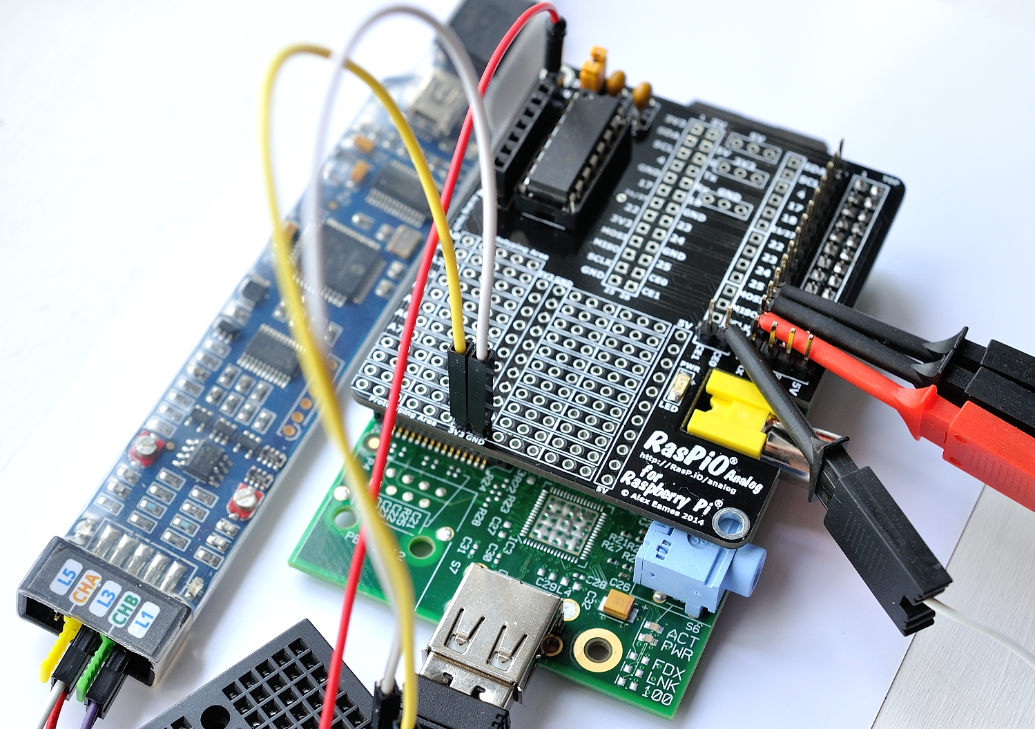
RasPiO Analog board + BitScope probes connected
I don’t claim to be an expert on SPI, but having spent the best part of a day playing with it, the mcp3008 data sheet and the BitScope Micro, I understand it a lot better now. Four pins are used…
- CEO – the chip select pin
- SCLK – the clock pin
- MOSI – Master Out, Slave In i.e. the Pi’s SPI output to mcp3008 input
- MISO – Master In, Slave Out i.e. the Pi’s SPI input from mcp3008 output
…and the way it works, at least my interpretation of it, follows the next large picture.
To Make an Interesting Pulse Pattern
Connecting 0V (00000000) or 3V3 (11111111) to the ADC gave a flat, boring MISO (ADC output) trace – All LOW (0V)…

MISO output at 0V
…or all HIGH (3V3)…

MISO output at 3V3
So I thought I’d try and get an alternating signal, e.g. 1010101010
To get the 1010101010 reading from the ADC, I had to convert 1010101010 to base 10, which is 682. Then, using a potentiometer, patience and Python, I tweaked the ADC input so the reading was exactly 0682 on the ADC (2.2V). Then I used the BitScope logic analyser with four probes hooked up to the SPI pins to capture the SPI signals. (L0 to MISO, L1 to MOSI, L2 to SCLK & L3 to CE0.)
For convenience, I connected them in the same order as the diagram in the mcp3008 data sheet (white overlay in the screenshot below). This makes it a bit easier to follow. (Although it’s a bit geeky if you’ve never done it before, and might take a little while to understand it clearly.) This is what the SPI signal traces look like when the ADC is reading a value of 0682. You can click the image to enlarge it, which makes the darkish colours of the SCLK & MOSI traces a bit easier to see.
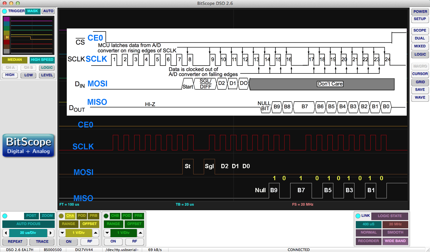
mcp3008 input/output signals for ADC value 0682 (1010101010)
Here’s a Walkthrough of the Diagram
When CE0 is brought LOW, the mcp3008 is activated (it is low for the whole of this screenshot, as that’s what I set as the BitScope trigger).
The Pi’s SPI clock pin, SCLK sends out 3 bytes (8 pulses each, 6 microseconds apart), which control the timing of the signals to and from the chip/pi.
On the 8th pulse of the first byte, MOSI sends a “START” bit, followed by four more bits (SGL, D2, D1, D0) to tell the ADC which mode and channel to use. In this case, single mode (1), channel 0 (0, 0, 0).
Thereafter, MOSI is ignored for the rest of this cycle.
Then the ADC reads the value of the voltage connected to its channel 0 input during the next clock pulse. After that, it uses the MISO port to output a null bit (0), followed by 10 data bits (B9-B0). These 10 bits are the binary value of the ADC reading. In our case, it’s 1010101010. You can see this in the bottom-right part of the logic trace (enlarged below)…

mcp3008 output (MISO) of 10101010
Note that B7 is wider because it spans the ‘gap’ between the second and third ‘bytes’ from the SCLK pin. This is expected, and appears in the data sheet diagram too.
When all the data has been ‘clocked out’ of the mcp3008, the CE0 chip select pin on the Pi is brought HIGH to end the transaction and deactivate the mcp3008.
It Was Nice to Confirm it
I’d seen these diagrams in data sheets before and only partially understood them. I’d ‘done’ the software side of it before. But through probing, poking, tweaking and adjusting, I now think I understand how the SPI protocol works in hardware for the mcp3008. To my mind, that’s a day very well spent! Education is priceless.
To those who think it’s all a bit weird, the main draw for many in science, engineering and programming is that “YES” (punch the air) feeling when you understand how or why something works and how you can “fiddle” with it to influence or control what it does.
And it’s all a part of my plan to take over the world. MwoaHaHaHaHaaaaa!