element14 Community
element14 Community
    Register Log In
  • Site
  • Search
  • Log In Register
  • About Us
  • Community Hub
    Community Hub
    • What's New on element14
    • Feedback and Support
    • Benefits of Membership
    • Personal Blogs
    • Members Area
    • Achievement Levels
  • Learn
    Learn
    • Ask an Expert
    • eBooks
    • element14 presents
    • Learning Center
    • Tech Spotlight
    • STEM Academy
    • Webinars, Training and Events
    • Learning Groups
  • Technologies
    Technologies
    • 3D Printing
    • FPGA
    • Industrial Automation
    • Internet of Things
    • Power & Energy
    • Sensors
    • Technology Groups
  • Challenges & Projects
    Challenges & Projects
    • Design Challenges
    • element14 presents Projects
    • Project14
    • Arduino Projects
    • Raspberry Pi Projects
    • Project Groups
  • Products
    Products
    • Arduino
    • Avnet Boards Community
    • Dev Tools
    • Manufacturers
    • Multicomp Pro
    • Product Groups
    • Raspberry Pi
    • RoadTests & Reviews
  • Store
    Store
    • Visit Your Store
    • Choose another store...
      • Europe
      •  Austria (German)
      •  Belgium (Dutch, French)
      •  Bulgaria (Bulgarian)
      •  Czech Republic (Czech)
      •  Denmark (Danish)
      •  Estonia (Estonian)
      •  Finland (Finnish)
      •  France (French)
      •  Germany (German)
      •  Hungary (Hungarian)
      •  Ireland
      •  Israel
      •  Italy (Italian)
      •  Latvia (Latvian)
      •  
      •  Lithuania (Lithuanian)
      •  Netherlands (Dutch)
      •  Norway (Norwegian)
      •  Poland (Polish)
      •  Portugal (Portuguese)
      •  Romania (Romanian)
      •  Russia (Russian)
      •  Slovakia (Slovak)
      •  Slovenia (Slovenian)
      •  Spain (Spanish)
      •  Sweden (Swedish)
      •  Switzerland(German, French)
      •  Turkey (Turkish)
      •  United Kingdom
      • Asia Pacific
      •  Australia
      •  China
      •  Hong Kong
      •  India
      •  Korea (Korean)
      •  Malaysia
      •  New Zealand
      •  Philippines
      •  Singapore
      •  Taiwan
      •  Thailand (Thai)
      • Americas
      •  Brazil (Portuguese)
      •  Canada
      •  Mexico (Spanish)
      •  United States
      Can't find the country/region you're looking for? Visit our export site or find a local distributor.
  • Translate
  • Profile
  • Settings
KEYSIGHT TECHNOLOGIES
  • Products
  • Manufacturers
  • KEYSIGHT TECHNOLOGIES
  • More
  • Cancel
KEYSIGHT TECHNOLOGIES
Forum component testing with keysight dsox1102g scope
  • Blog
  • Forum
  • Documents
  • Events
  • Polls
  • Files
  • Members
  • Mentions
  • Sub-Groups
  • Tags
  • More
  • Cancel
  • New
Join KEYSIGHT TECHNOLOGIES to participate - click to join for free!
Actions
  • Share
  • More
  • Cancel
Forum Thread Details
  • State Suggested Answer
  • Replies 40 replies
  • Answers 25 answers
  • Subscribers 21 subscribers
  • Views 5717 views
  • Users 0 members are here
  • component tester
  • elenco
  • short
Related

component testing with keysight dsox1102g scope

johnwater
johnwater over 5 years ago

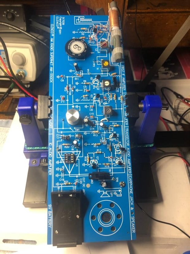
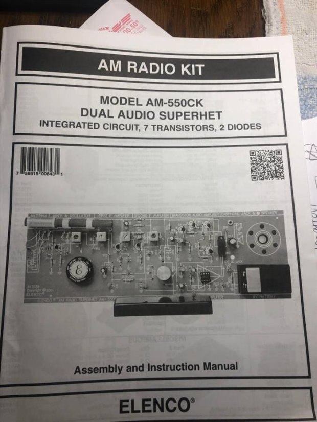
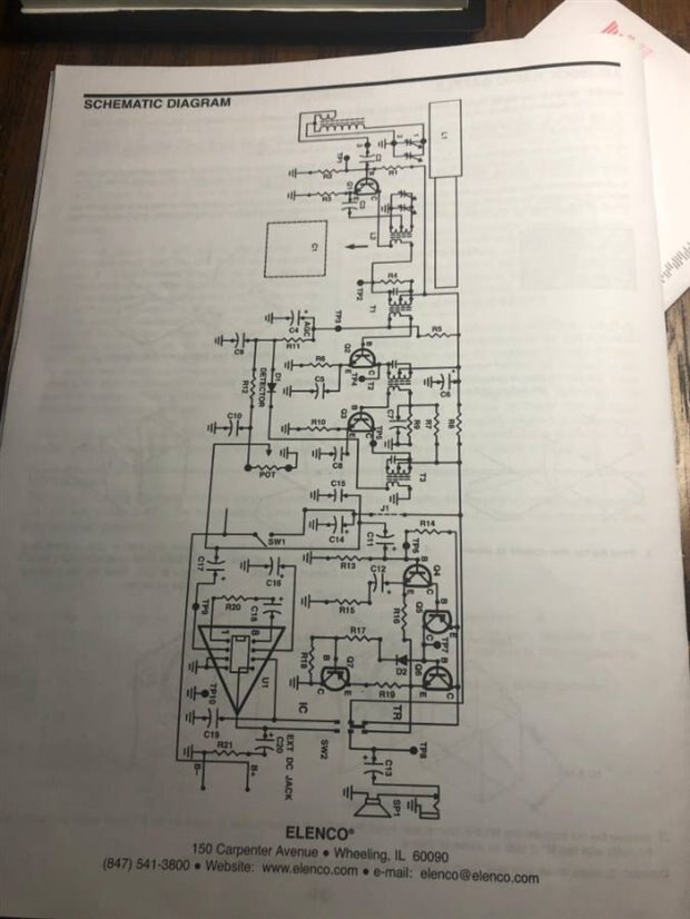
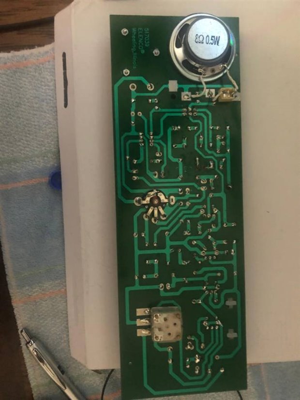
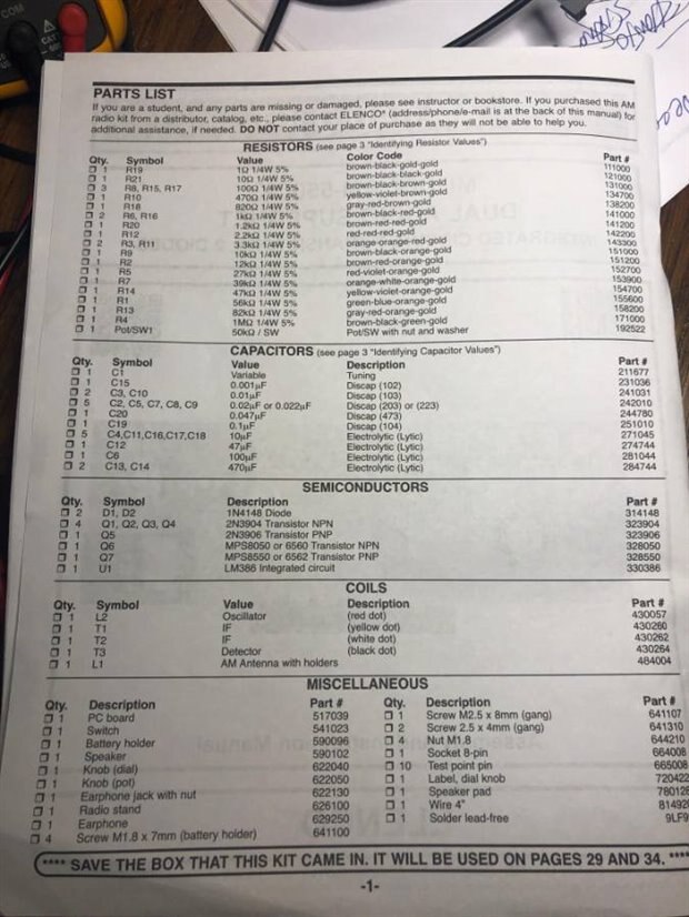
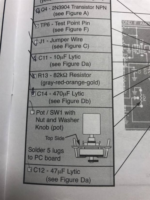
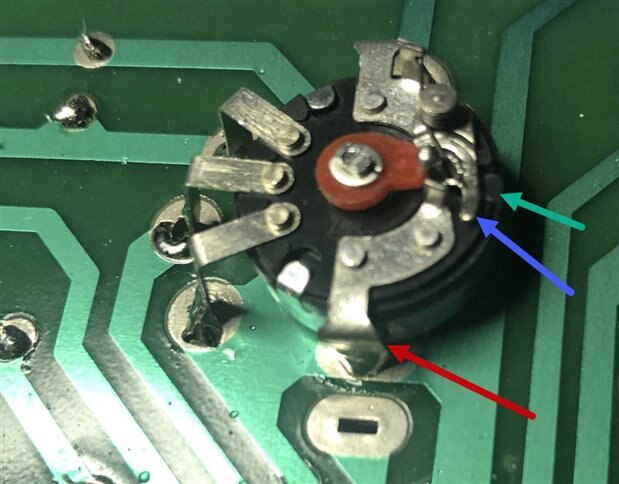
hello would like to learn how to measure components on my elenco am radio kit.

am new to electronics, trying to figure things out.

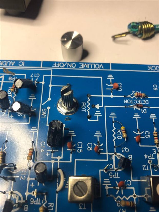
read about lissajous patterns, just need some direction as to how to set up my connections, see if components are functioning as necessary.

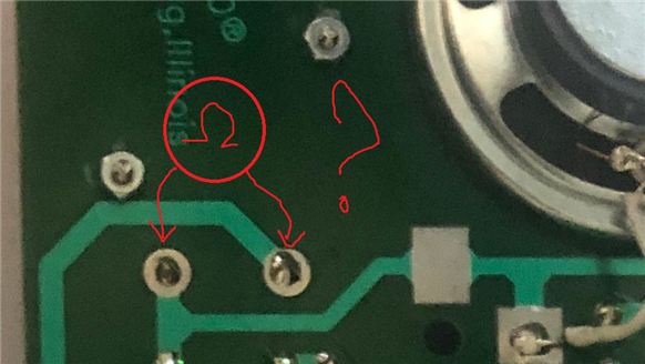
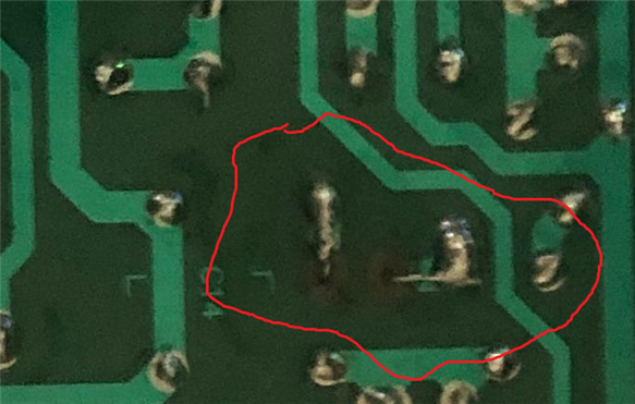
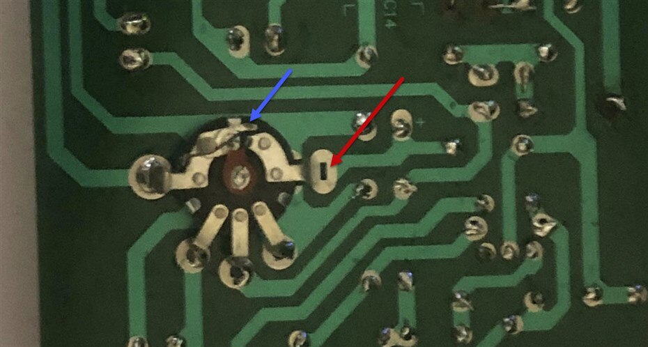
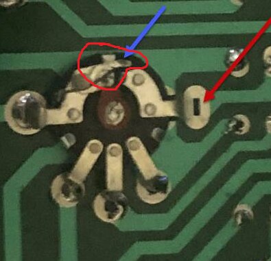
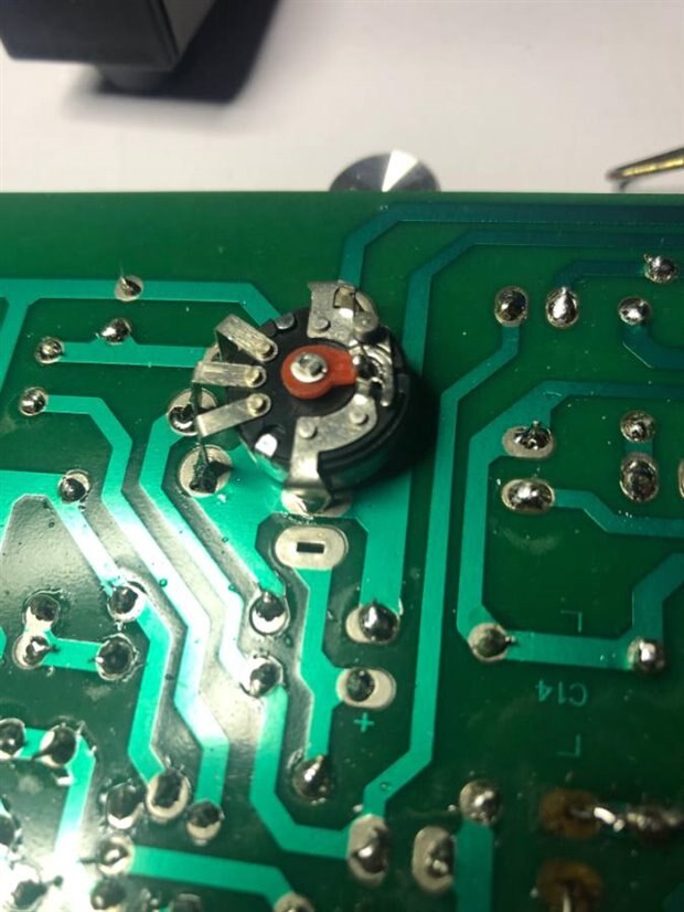
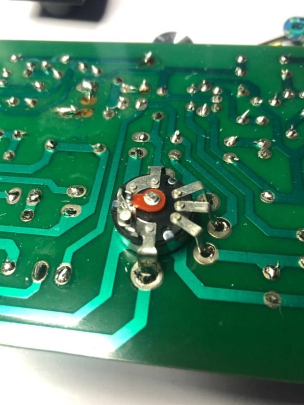
my 9 volt battery gets hot, no audio output,so  i think i have short somewhere?

thanks

john

  • Sign in to reply
  • Cancel

Top Replies

  • Jan Cumps
    Jan Cumps over 5 years ago in reply to johnwater +4 suggested
    The soldering is good. I see that most of the transistors are NPN. There's 2 PNPs that I can see (Q5, Q7). You have different part numbers for those? Electrolytic capacitors look correct (I can't see the…
  • Jan Cumps
    Jan Cumps over 5 years ago in reply to shabaz +4 suggested
    Looking at the potentiometer, it seems that it has been inserted from the wrong side (inserted from above instead of pushed in from the underside).. The movable switch part looks forced (blue), and the…
  • Jan Cumps
    Jan Cumps over 5 years ago in reply to fmilburn +4 suggested
    I think that the second pin of the switch is soldered to the wrong hole:
Parents
  • Jan Cumps
    0 Jan Cumps over 5 years ago

    A photo of front and backside of your device would maybe help. We can help check if something is wrong or if there are possible bridges. Meanwhile, don't put the battery in.

    A battery running hot on an AM radio points to a shortcut.

    • Cancel
    • Vote Up 0 Vote Down
    • Sign in to reply
    • Verify Answer
    • Cancel
  • johnwater
    0 johnwater over 5 years ago in reply to Jan Cumps

    thanks jan

    yes i can post pics of back and front.took battery Outland ic also.

    have looked on front and back by solders, but my untrained eye fails to pick up anything obvious.

    if u see something, let me know.

    johnimageimageimageimage

    • Cancel
    • Vote Up +2 Vote Down
    • Sign in to reply
    • Verify Answer
    • Reject Answer
    • Cancel
Reply
  • johnwater
    0 johnwater over 5 years ago in reply to Jan Cumps

    thanks jan

    yes i can post pics of back and front.took battery Outland ic also.

    have looked on front and back by solders, but my untrained eye fails to pick up anything obvious.

    if u see something, let me know.

    johnimageimageimageimage

    • Cancel
    • Vote Up +2 Vote Down
    • Sign in to reply
    • Verify Answer
    • Reject Answer
    • Cancel
Children
  • Jan Cumps
    0 Jan Cumps over 5 years ago in reply to johnwater

    The soldering is good. I see that most of the transistors are NPN. There's 2 PNPs that I can see (Q5, Q7). You have different part numbers for those?

    Electrolytic capacitors look correct (I can't see the symbol under C13 but when viewing the schematic, it looks that it's correct too).

    The diode is correct too.

    I don't see anything obvious.

    What is the resistance if you take out the battery and measure over the two solder points of the battery housing?

    image


    Maybe double-check if this is repaired correctly:

    image

    • Cancel
    • Vote Up +4 Vote Down
    • Sign in to reply
    • Verify Answer
    • Reject Answer
    • Cancel
  • shabaz
    0 shabaz over 5 years ago in reply to johnwater

    Also, this bit looked strange:

    image

    Is something missing where the red arrow is pointing at a rectangular slot? To me it looks like the switch (marked with blue arrow) isn't connecting, because nothing is connected to that rectangular slot, so power cannot be enabled into the circuit.

    It doesn't explain how the battery could be getting hot though! That's the opposite to what would be expected..

    Maybe a second photo is needed of the PCB, I just can't tell from that angle.

    • Cancel
    • Vote Up +3 Vote Down
    • Sign in to reply
    • Verify Answer
    • Reject Answer
    • Cancel
  • Jan Cumps
    0 Jan Cumps over 5 years ago in reply to shabaz

    Looking at the potentiometer, it seems that it has been inserted from the wrong side (inserted from above instead of pushed in from the underside)..

    The movable switch part looks forced (blue), and the right connector of the switch is above the PCB instead of below, on the solder pad (red).

    • Cancel
    • Vote Up +4 Vote Down
    • Sign in to reply
    • Verify Answer
    • Reject Answer
    • Cancel
  • Jan Cumps
    0 Jan Cumps over 5 years ago in reply to Jan Cumps

    The unsoldered contact can't create a shortcut.

    But this may be the cause:

    image

    • Cancel
    • Vote Up +3 Vote Down
    • Sign in to reply
    • Verify Answer
    • Reject Answer
    • Cancel
  • shabaz
    0 shabaz over 5 years ago in reply to Jan Cumps

    Ah, I see, you're right... You mean the switch pole is bent and hitting the shell, right? Yep, that could do it, if the wiper is touching to the shell and the volume is turned down : (

    I'm so used (like you probably) to seeing this type of reverse-mounted switch/pot from 20th century consumer radios : ) but I can see it could be a confusing component for any newcomer wishing to solder it on!

    • Cancel
    • Vote Up +3 Vote Down
    • Sign in to reply
    • Verify Answer
    • Cancel
  • johnwater
    0 johnwater over 5 years ago in reply to Jan Cumps

    the poles between the battery solders is infinity 0L.


    the other area circled was a screw up of mine where the copper shield came off.Called elenco and tech said to just solder longer leads to meet the other connections, which i did.these aeremitter of Q4 and+ of capacitor C12,and negative lead of C12 to resistor  R15.and they all show good continuity..

    i should have enclosed a parts list for you.

    thanks

    johnimage

    • Cancel
    • Vote Up +1 Vote Down
    • Sign in to reply
    • Verify Answer
    • Reject Answer
    • Cancel
  • johnwater
    0 johnwater over 5 years ago in reply to shabaz

    i took the knob off of pot so we can see underside better.the nut and washer fit on top side of board, there are 5 lugs to solder on bottom of pc board.

    looking at 3 of the lugs i will re-solder those to fill holes better,

    everything is soldered from the bottom ,not on top of board.

    how would i check to see if this pot is shorting out somewhere?

    johnimageimageimageimage

    • Cancel
    • Vote Up +2 Vote Down
    • Sign in to reply
    • Verify Answer
    • Reject Answer
    • Cancel
  • shabaz
    0 shabaz over 5 years ago in reply to johnwater

    Hi John,


    You can use your multimeter set to ohms to check any component that isn't in-circuit any more.

    1. Is the metal indicated to by the red arrow soldered or touching the body/shell metalwork? I don't understand why it isn't soldered to the adjacent rectangular slot in the PCB, basically. And also, if it is touching the shell, or soldered to it, that could be an issue.

    2. What's the resistance between the shell, and each of the three contacts for the variable resistor?

    3. And also, is the switch mechanism (blue arrow) touching the shell tab (green arrow)? If so, that could be an issue too, because it isn't supposed to be touching the shell tab. Again, this can be verified by the multimeter set to ohms and measuring from the switch contacts to the metal shell (do this for both of the switch contacts).


    An understanding of what this component is doing is needed; two of the contacts are intended to work as a switch, and the remainder three contacts serve as the potentiometer or variable resistor. The switch contacts should be electrically isolated (i.e. extremely high resistance, 0L on your meter) from the three potentiometer contacts _and_ the shell. If that's not the case, there is an issue.

    image

    • Cancel
    • Vote Up +1 Vote Down
    • Sign in to reply
    • Verify Answer
    • Reject Answer
    • Cancel
  • johnwater
    0 johnwater over 5 years ago in reply to shabaz

    shabazi believe you are right.

    one of the wiper pins is physically touching the base of switch,vom shows low resistance, almost like a short.

    i am going to take whole switch off and realign and report back .

    thanks

    john

    • Cancel
    • Vote Up +4 Vote Down
    • Sign in to reply
    • Verify Answer
    • Reject Answer
    • Cancel
  • Jan Cumps
    0 Jan Cumps over 5 years ago in reply to johnwater

    Taking off the switch is not easy, once the pins are soldered. It may be easier to try and desolder only that one that's mounted in the wrong hole, and place it in the correct hole.

    If you can't get it out, clip it as close to the PCB as you can, then use some wire to bridge the gap.

    It will impact the strength of the construction though. The 2 switch contacts also play a role to keep the potentiometer from twisting in place ...

    • Cancel
    • Vote Up +3 Vote Down
    • Sign in to reply
    • Verify Answer
    • Reject Answer
    • Cancel
element14 Community

element14 is the first online community specifically for engineers. Connect with your peers and get expert answers to your questions.

  • Members
  • Learn
  • Technologies
  • Challenges & Projects
  • Products
  • Store
  • About Us
  • Feedback & Support
  • FAQs
  • Terms of Use
  • Privacy Policy
  • Legal and Copyright Notices
  • Sitemap
  • Cookies

An Avnet Company © 2025 Premier Farnell Limited. All Rights Reserved.

Premier Farnell Ltd, registered in England and Wales (no 00876412), registered office: Farnell House, Forge Lane, Leeds LS12 2NE.

ICP 备案号 10220084.

Follow element14

  • X
  • Facebook
  • linkedin
  • YouTube