

Application Note
Derating of Connectors
![]()
ANE006 BY ALEXANDRE CHAILLET
1 Introduction
We know that electrical resistance creates heat when a current goes through it. The amount of heat is directly related to these two parameters. But what is the influence of the ambient temperature on the resistance? Should we limit the current when the temperature increases and especially when it is close to the maximum operating temperature allowed on a connector?
We will try to answer these questions and give practical operating curves to be used with our connectors.
2 Temperature Rise
2.1. Temperature rise theory
Electrical connectors always specify a working current which is defined by international, national or even industry specific standards that provide a maximum temperature rise (Δt) value allowed under working current. These are measured at the hottest point of the connector by using a very precise processes (usually EIA364-70 standard is followed).
Different standards might allow different values for this maximum Δt. For UL certification, Würth Elektronik chose to have a Δt maximum of 30 K (UL1059 – Terminal blocks).
Different standards can refer to different test procedures, the number of poles and especially Δt value hence it is possible to find different current values within the standards (UL and VDE for example) for the same product.
Δt can be calculated by the following Joule formula.
 (1)
(1)
With:
Δt temperature rise in Kelvin
k constant
R connector resistance in Ω
I current in A
The k constant depends on environmental factors like: type of plastic material and even its color, air flow and all factors that will improve or reduce thermal dissipation. We, of course, cannot know or calculate it easily for each type of product use.
It is possible to omit this constant from the calculation when we compare values on the same system. If we measure Δt1 of a connector with a current I1, Δt2 can be calculated at a different current I2 without any measurement.
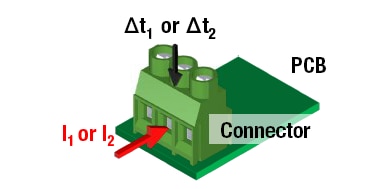
Figure 1: Temperature rise test principle
If we use Joule’s formula (Equation 1), constant k and resistance R will be the same for these two lines.
 (2)
(2)
Note: This formula is an estimation and therefore not precise because of the following reasons: injected current precision, measurement precision and environment.
We will see in the next paragraph if this estimation is accurate compared to real measurements.
The internal temperature of the connector is
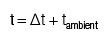 (3)
(3)
2.2. Temperature rise experiment
We performed the temperature rise test to some of our products to validate the theory. The products were placed inside an enclosed space to avoid the influence of air flow. There was no temperature regulation.
In the following example a PCB terminal block is connected with its three poles in series. Then a current of 20 A is applied using a 12 AWG wire. Three thermocouples are placed on the connector, one inside of each screw clamp, an additional thermocouple is used to measure the ambient temperature.
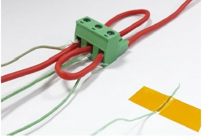
Figure 2: Test cabling
Table 1 shows the results of the thermocouple Δt measurement (in K) and in parallel the calculated estimation using Joule’s formula with the Δt at working current 20 A (green line).
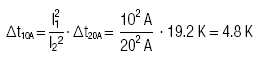
As an example, the estimation of Th1 at 10 A is calculated as follows:
 (4)
(4)
From the experimental results shown in Table 1, we notice that going from 10 A to 20 A the temperature rise of the connector multiplies by the factor of four! The prediction error (in K) is the average of each the three errors between measured and calculated value.
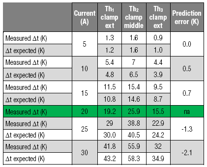
Table 1: ΔT test results compared with estimation calculation
Prediction error shows that the calculation method is an valid approach to estimate the real Δt value. It means that if you know Δt of a connector at a current you can estimate Δt at another current.
Be aware that this estimation is less accurate if there is a large difference between the two currents used (2 A and 50 A for example).
3 Derating Testing
3.1. Derating Theory and Experimentation
Derating testing is a Δt test performed at the working current which is performed in climatic chamber at different temperatures, normally from 20°C up to the maximum operating temperature allowed for the product. It provides us information regarding the maximum current allowed under different thermal conditions.
Würth Elektronik products are designed so that metal parts do not lose their efficiency across the working temperature range. However we see a sensible Δt variation with temperature.
The main reason is that metal electrical resistances vary with temperature according to the following formula:
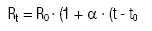 (5)
(5)
With:
Rt resistance of a metal conductor at a temperature t in Ω
R0 resistance at a temperature t0 in Ω
α temperature coefficient of resistance in K-1
t temperature in °C (or K)
α is a material dependant constant. Two examples of materials widely used as conductors:
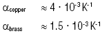
Note: The symbol '≈' is used because the value varies slightly with material grade.
Obviously, the overall contact resistance is the addition of different parameters: different material conductors, contact between wire and clamp, soldering and contact between mated terminals.
To give an idea of the resistance variation on a connector with a mix between copper and brass conductors, using as an example the temperature variation from 20 °C to 100 °C, this can be estimated using the following calculation:
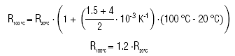 (6)
(6)
This example shows that the connector will increase its resistance by approximately 20%.
Table 2 shows some measurements at different temperatures.
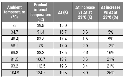
Table 2: Table of derating test values for a pluggable terminal block
We must remember that the temperature rise is directly proportional to the connector resistance. When we take this into account the estimation of the resistance increase is consistent.
3.2. Derating Curves
We previously saw that working current allows a temperature rise of 30 K maximum according to the UL Standard used. We saw that the electrical resistance of a metal part would naturally increase due to the increase of the ambient temperature.
We know that all products have a working temperature range and especially a maximum operating temperature to be used under.
Now the question is ”Can the product be used with the maximum working current at the maximum temperature allowed”?
The answer is we should adjust the current to avoid excessive temperature on the product as this will decrease its life time. We should follow the derating curves.
They are designed as follows:
- Working current is of course allowed from the minimum operating temperature. The curves start from 0 °C to avoid a long flat curve area.
- For UL standard, from “tmax - 30 K” to maximum operating temperature, current will decrease according to the square of the current.
- For VDE standard, from “tmax - 45 K” to maximum operating temperature
For a product with a maximum operating temperature for example of 85 °C, we could estimate the following derating curves in Figure 3 and Figure 4 (red line).
The increased resistance is taken in account because Würth Elektronik uses a safety margin of 20% against the working current obtained during the derating test.
The additional lines are the derating curves for our connectors according to the maximum operating temperature specified. These can be used for any of our eiCan products.
4 Summary
If we know the temperature rise Δt1 (in K) for a connector under a current I1 (in A), it is possible to estimate the temperature rise Δt2 under a different current I2.
 (7)
(7)
Note: This formula is for the same connector under the same environmental conditions.
When a connector is used close to the maximum temperature allowed, it is recommended to use derating curves that are given in this application note paragraph 3.2. They are applicable for all eiCan products.
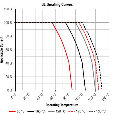
Figure 3: UL derating curves for different operating temperatures
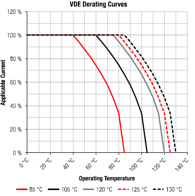
Figure 4: VDE derating curves for different operating temperatures
IMPORTANT NOTICE
The Application Note is based on our knowledge and experience of typical requirements concerning these areas. It serves as general guidance and should not be construed as a commitment for the suitability for customer applications by Würth Elektronik eiSos GmbH & Co. KG. The information in the Application Note is subject to change without notice. This document and parts thereof must not be reproduced or copied without written permission, and contents thereof must not be imparted to a third party nor be used for any unauthorized purpose.
Würth Elektronik eiSos GmbH & Co. KG and its subsidiaries and affiliates (WE) are not liable for application assistance of any kind. Customers may use WE’s assistance and product recommendations for their applications and design. The responsibility for the applicability and use of WE Products in a particular customer design is always solely within the authority of the customer. Due to this fact it is up to the customer to evaluate and investigate, where appropriate, and decide whether the device with the specific product characteristics described in the product specification is valid and suitable for the respective customer application or not.
The technical specifications are stated in the current data sheet of the products. Therefore the customers shall use the data sheets and are cautioned to verify that data sheets are current. The current data sheets can be downloaded at www.we-online.com. Customers shall strictly observe any product-specific notes, cautions and warnings. WE reserves the right to make corrections, modifications, enhancements, improvements, and other changes to its products and services.
WE DOES NOT WARRANT OR REPRESENT THAT ANY LICENSE, EITHER EXPRESS OR IMPLIED, IS GRANTED UNDER ANY PATENT RIGHT,
COPYRIGHT, MASK WORK RIGHT, OR OTHER INTELLECTUAL PROPERTY RIGHT RELATING TO ANY COMBINATION, MACHINE, OR PROCESS IN WHICH WE PRODUCTS OR SERVICES ARE USED. INFORMATION PUBLISHED BY WE REGARDING THIRD-PARTY PRODUCTS OR SERVICES DOES NOT CONSTITUTE A LICENSE FROM WE TO USE SUCH PRODUCTS OR SERVICES OR A WARRANTY OR ENDORSEMENT THEREOF.
WE products are not authorized for use in safety-critical applications, or where a failure of the product is reasonably expected to cause severe personal injury or death. Moreover, WE products are neither designed nor intended for use in areas such as military, aerospace, aviation, nuclear control, submarine, transportation (automotive control, train control, ship control), transportation signal, disaster prevention, medical, public information network etc. Customers shall inform WE about the intent of such usage before design-in stage. In certain customer applications requiring a very high level of safety and in which the malfunction or failure of an electronic component could endanger human life or health, customers must ensure that they have all necessary expertise in the safety and regulatory ramifications of their applications. Customers acknowledge and agree that they are solely responsible for all legal, regulatory and safety-related requirements concerning their products and any use of WE products in such safety-critical applications, notwithstanding any applications-related information or support that may be provided by WE.
CUSTOMERS SHALL INDEMNIFY WE AGAINST ANY DAMAGES ARISING OUT OF THE USE OF WE PRODUCTS IN SUCH SAFETY-CRITICAL APPLICATIONS.
DIRECT LINK
USEFUL LINKS:
Application Notes : https://we-online.com/en/support/knowledge/application-notes
Services: https://we-online.com/en/products/components/service
Contact : https://we-online.com/en/support/contact
CONTACT INFORMATION
Würth Elektronik eiSos GmbH & Co. KG
Max-Eyth-Str. 1, 74638 Waldenburg, Germany
Tel.: +49 (0) 7942 / 945 – 0
Email: appnotes@we-online.de
Web: https://www.we-online.com