Application Note
Inrush current for connectors
ANE015 BY ALEXANDRE CHAILLET, JULIEN HENROT
1 Introduction
This application note is related to Würth Elektronik TBL series terminal blocks only.
All resistors carrying current release heat, which is called the Joule effect. A power connector can be considered as a simple resistor from a thermal point of view. The working current of a power connector is usually defined by a standard, in our case by UL 1059. The maximum temperature rise (∆T) in the standard is 30 K (∆T is usually given in Kelvin and temperature in °Celsius).
 Eq.(1)
This means that at full working current, the connector’s internal temperature will not exceed 30 K more than ambient temperature. The temperature rise plus the ambient temperatire (Eq.(1)) are limited by the maximum operating temperature rating. Used with the proper derating curve, working current ensures connector durability (for more details have a look at ANE006 Derating of connectors). Some applications require a high current for a short duration, for example for a short acceleration of an electric scooter or transition phase of an electric transformer or capacitance discharge for lighting ballast. Do we have to oversize the connector working current with this inrush current or is it possible to go above working current for a short period of time?
2 Temperature rise under current
2.1. Working current temperature rise
Temperature rise could be written as following:
 Eq. (2)
With:
∆T temperature rise [K]
k thermal environment constant
R connector resistance [Ω]
I current [A]
The environment (ambient plus mounting) has a big influence on the thermal behavior of a connector. It will define how quickly thermal energy will be dissipated or not. That is why k is defined as a constant.
However, it is not possible to define k for each condition and so we prefer to compare temperature rise under the same conditions. That will remove the constant as we see in Equation (3). Thermal equilibrium is reached when the calories from the Joule effect and the calories dissipated by the connector are equal.
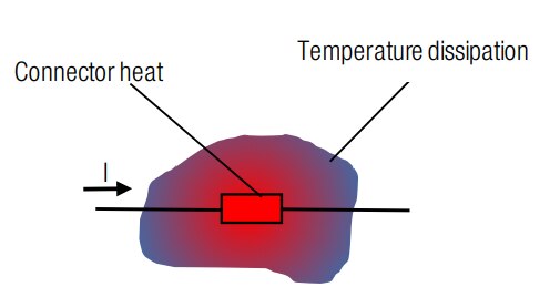
Figure 1: Connector thermal dissipation schematic
Figure 2 gives an example of a common connector temperature rise measurment over the time, of course ∆T < 30 K. As we can see, several minutes are needed for the system to stabilize the temperature increase.
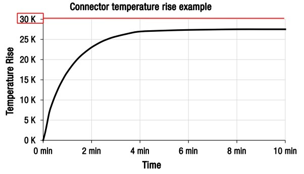
Figure 2: Connector temperature rise in minutes
2.2. Temperature rise time under current
Now let’s focus the first minute of the test that was described on the figure 2. Figure 3 is the same curve but just for the first 60 seconds. We see for example, at 10 s that ∆T = 5 K:
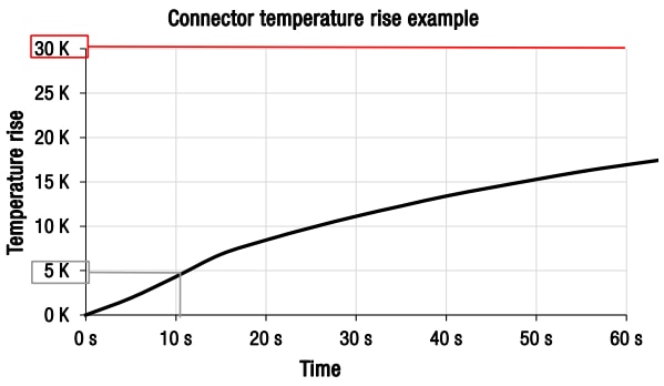
Figure 3 : Temperature rise during the first minute
We can assume, that the current could be above the working current for a short period of time without reaching ∆T = 30 K.
The question is, how to estimate the current per period of time in a connector without exceeding a temperature rise of 30 K?
3 Inrush Current
3.1. Pre-test: inrush current duration that gives a ∆T of 30 K
We will work this out by experiment by pushing the connectors over the nominal working current. Each test stops at 100°C, so as to not to exceed maximum operating temperature.
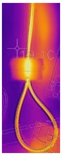
Figure 4: TBL over-current test at ambient temperature of 19.1°C
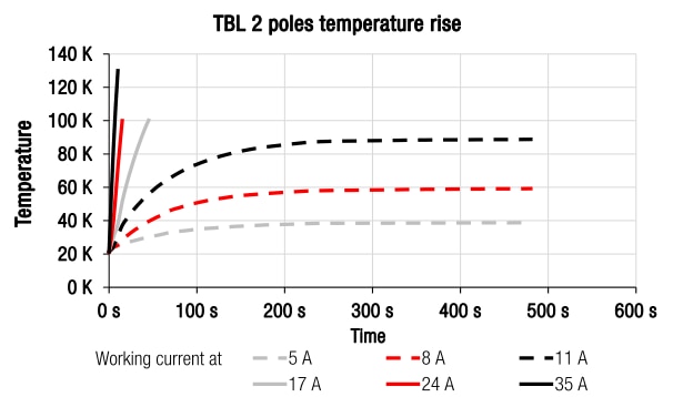
Figure 5: Temperature rise above the rated working current of 5 A Conclusions from curves:
- Working current gives a ∆T < 30 K as requested by UL standard
- Going higher than working current obviously exceeds 30 K
- If we limit the duration, it is possible to keep the connector ∆T < 30 K. For example, with this connector, we are able to apply 11 A (2.2 times working current) for a duration of 35 s to reach 30 K.
3.2. Inrush current curve proposal:
Now we need to find out how long we could apply a current over nominal value, and to finally test it on some of our connectors to validate the inrush current and time. We have chosen a large safety factor of greater than two between what we have measured and what we finally state in our datasheet.
3.3. Inrush current full tests
A series of connectors with a characteristic number of contacts was tested (red curve in figure 6) to check that the load from the increased current has no unacceptable effects on the connector. All values marked by the 10 red dots in figure 7 had to be tested on each connector (e.g. 1.1 times working current during 20 s). The aim was to verify that ∆T does not exceed 30 K for each point.
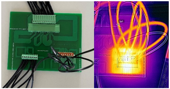
Figure 6: Set-up of the inrush current test
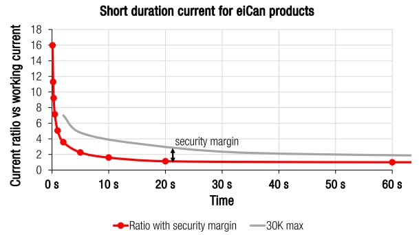
Figure 7: Typical 30 K temperature rise current and proposal with safety margin

Figure 8: Inrush current test results
Ten tests were carried out with different currents, with an interval of 5 minutes to allow the temperature to slowly return to the initial value. The first ∆T-peak is the largest. It refers to the working current during a period of 10 minutes. All other "working points" have a very small effect on the ∆T, here about 5 K maximum.
3.4. Conclusions from the tests
All tests carried out with different products showed roughly similar results. Thermal energy must be dissipated to the ambient surrounding the connector. Otherwise the energy is accumulated inside the connector. In that case, the temperature would continue to increase and put in danger the electrical parts or even worse the whole appliance. Figure 9 shows a connector at 70 % of the nominal current with 10 peaks of current with a ratio of 7:1 (peak to nominal) and an interval of 5 minutes, that is necessary to let the connector return to its initial temperature.
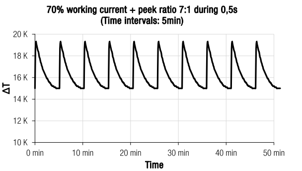
Figure 9: ∆T curve with enough time interval between peaks for energy dissipation
When the temperature rise always returns to 15 K, the system is stable. But if the time interval is reduced, the thermal energy does not have enough time to be dissipated. Figure 10 shows, that the temperature continues to increase. The system is not stable. After a period of time, this will damage the connector so, this condition must be avoided.
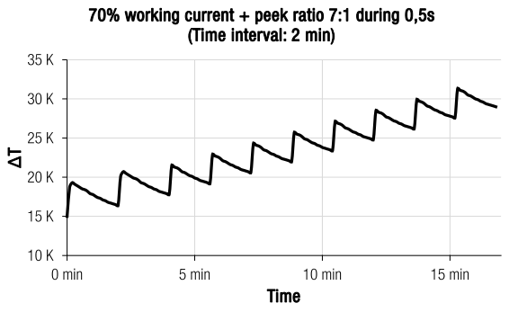
Figure 10: ∆T curve with a time interval between peaks that is too short for sufficient energy dissipation
Energy dissipation strongly depends on the connectors environment: size of PCB traces, size of wires, in a closed box or not. The amount of energy dissipation, at the 5 minute intervals given here, varies with respect to each application.
4 Final applicable curves
4.1. Inrush current curve
Finally, it is possible to have an inrush peak current every 5 minutes (minimum to be verified on real conditions) for each connector following the curves in Figures 11 and 12.
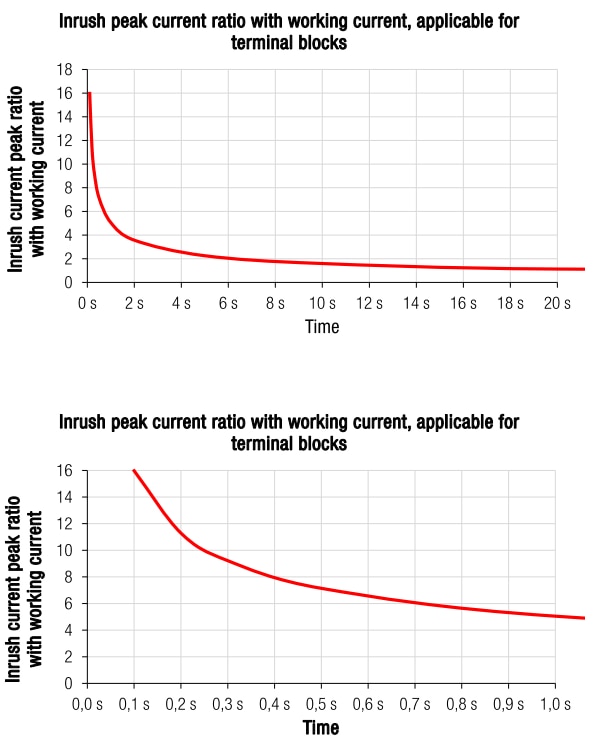
Figure 11 & 12: Close-up of applicable inrush current for WE connectors. Note different time scales
Example: With a working current of 5 A, it is possible to use it at full current and every 5 minutes have a peak current of, e.g., two times the working current (10 A) for 6 seconds.
4.2.Derating curve – constant “inrush” current
If a WE connector is used, the following curve gives the current applicable related to the operating temperature (Figure 13). Würth Elektronik complies with UL regulations in every situation. A maximum temperature rise of ∆T ≤ 30 K is set, regardless of which inrush current is applied. It is therefore not possible to operate a connector with full current and additional inrush current at the same time.
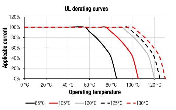
Figure 13: UL derating curves for different operating temperatures
For safety reasons, we assume that the maximum ∆T at inrush current is 15 K. This means that a maximum ∆T for the temperature rise at stable current of 30 -15 = 15 K is possible. With Eq 2, for the same system, we know that ∆T is given by following formula:
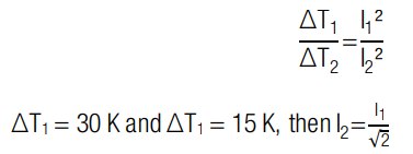 Eq. (3)
With inrush current, we have to limit the working current to

So finally, if we want to use a connector with both, the continuous and the inrush current, we need to adjust the derating curves as follows:

Figure 14: UL derating curves for continuous and inrush current at different operating temperatures. For WE terminal blocks only
Remember to always do a temperature rise test in real conditions to confirm that the time interval is long enough to keep system stable.
5 Summary
Basic rules:
- Max temperature < connector operating temperature
- Max ∆T < 30 K in all cases (UL)
- It is recommended to let at least 5 minutes pass between two surges to allow the temperature to decrease to the initial temperature.
- Each situation is different regarding its thermal dissipation capabilities, so each application must be validated (customer must verify that ∆T remains < 30 K in any case) by the customer in real conditions.
The curves in this application note are recommendations. However, Würth Elektronik guarantees the paramters specified in the data sheets. Furthermore, adjusting the inrush current according to the application and the ambient temparature is the responsibility of the customer.
IMPORTANT NOTICE
The Application Note is based on our knowledge and experience of typical requirements concerning these areas. It serves as general guidance and should not be construed as a commitment for the suitability for customer applications by Würth Elektronik eiSos GmbH & Co. KG. The information in the Application Note is subject to change without notice. This document and parts thereof must not be reproduced or copied without written permission, and contents thereof must not be imparted to a third party nor be used for any unauthorized purpose. Würth Elektronik eiSos GmbH & Co. KG and its subsidiaries and affiliates (WE) are not liable for application assistance of any kind. Customers may use WE’s assistance and product recommendations for their applications and design. The responsibility for the applicability and use of WE Products in a particular customer design is always solely within the authority of the customer. Due to this fact it is up to the customer to evaluate and investigate, where appropriate, and decide whether the device with the specific product characteristics described in the product specification is valid and suitable for the respective customer application or not. The technical specifications are stated in the current data sheet of the products. Therefore the customers shall use the data sheets and are cautioned to verify that data sheets are current. The current data sheets can be downloaded at www.we-online.com. Customers shall strictly observe any product-specific notes, cautions and warnings. WE reserves the right to make corrections, modifications, enhancements, improvements, and other changes to its products and services. WE DOES NOT WARRANT OR REPRESENT THAT ANY LICENSE, EITHER EXPRESS OR IMPLIED, IS GRANTED UNDER ANY PATENT RIGHT, COPYRIGHT, MASK WORK RIGHT, OR OTHER INTELLECTUAL PROPERTY RIGHT RELATING TO ANY COMBINATION, MACHINE, OR PROCESS IN WHICH WE PRODUCTS OR SERVICES ARE USED. INFORMATION PUBLISHED BY WE REGARDING THIRD-PARTY PRODUCTS OR SERVICES DOES NOT CONSTITUTE A LICENSE FROM WE TO USE SUCH PRODUCTS OR SERVICES OR A WARRANTY OR ENDORSEMENT THEREOF. WE products are not authorized for use in safety-critical applications, or where a failure of the product is reasonably expected to cause severe personal injury or death. Moreover, WE products are neither designed nor intended for use in areas such as military, aerospace, aviation, nuclear control, submarine, transportation (automotive control, train control, ship control), transportation signal, disaster prevention, medical, public information network etc. Customers shall inform WE about the intent of such usage before design-in stage. In certain customer applications requiring a very high level of safety and in which the malfunction or failure of an electronic component could endanger human life or health, customers must ensure that they have all necessary expertise in the safety and regulatory ramifications of their applications. Customers acknowledge and agree that they are solely responsible for all legal, regulatory and safety-related requirements concerning their products and any use of WE products in such safetycritical applications, notwithstanding any applications-related information or support that may be provided by WE. CUSTOMERS SHALL INDEMNIFY WE AGAINST ANY DAMAGES ARISING OUT OF THE USE OF WE PRODUCTS IN SUCH SAFETY-CRITICAL APPLICATIONS.
DIRECT LINKS
ANE15: Inrush current for connectors
USEFUL LINKS:
Application Notes : https://we-online.com/en/support/knowledge/application-notes
Services: https://we-online.com/en/products/components/service
Contact : https://we-online.com/en/support/contact
CONTACT INFORMATION
Würth Elektronik eiSos GmbH & Co. KG
Max-Eyth-Str. 1, 74638 Waldenburg, Germany
Tel.: +49 (0) 7942 / 945 – 0
Email: appnotes@we-online.de

