APPLICATION NOTE
Coaxial cables and cable assemblies
ANE016 BY Jason Chang
01. INTRODUCTION
The function of a coaxial cable is to deliver a RF signal from point A to point B through various connector interfaces. Würth Elektronik offers a wide range of quality cable assemblies. This application note is based on Würth Elektronik standard cable types and helps to understand which points to consider when selecting a cable for custom tailored cable assemblies.
02. IDENTIFY A COAXIAL CABLE
Coaxial cable is a type of transmission line used to carry high-frequency electrical signals with low losses. It differs from electrical wire and other shielded cables because the dimensions of the cable and connectors are controlled to give a precise, constant conductor spacing, which is needed for it to function efficiently as a transmission line.
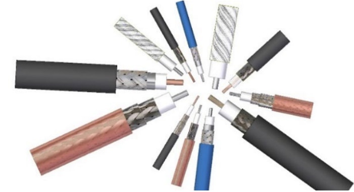
Figure 1: Coaxial cables
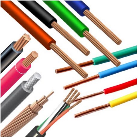
Figure 2: Electrical Wires
Coaxial cable conducts the electrical signal using a center conductor [1] surrounded with a dielectric layer [2] and enclosed by shielding [3] (typically one to four layers of woven metallic braid or tape). Most coaxial cables are protected by an outer non-conducting jacket [4].
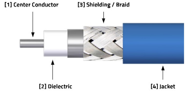
Figure 3: Cable view
Standard materials used for each of the parts:
- Center Conductor Solid or stranded Cu
- Dielectric PTFE, FEP
- Shielding / Braid Single or double layer
- Jacket PVC, PE, FEP
03. COAXIAL CABLE TYPE OVERVIEW AND SELECTION POINTS
The goal of this section is to help the user determine the appropriate coaxial cable type for an application according to each cable’s characteristics. To reach this goal, table 1 gives an overview of common cables and their properties. Using the table we can walk through coaxial cable selection step by step. The coaxial cable portfolio from Würth Elektronik is covers two main cable types:
- 50 Ω Flexible cable
- 50 Ω Hand-formable cable
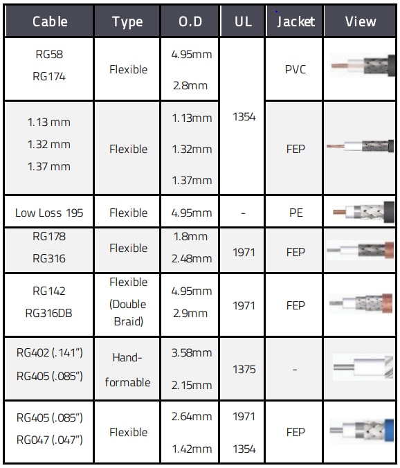
Table 1 : WE standard coaxial cable type overview
Most coaxial cables are identified by a RG (radio guide) number which is a designation given by a military specification. Cables vary by size, conductor, dielectric, shielding and jacket materials. The different RG numbers for each type of coax cable are helpful to distinguish their unique characteristics and specifications though the numbers themselves do not have any specific meaning. Underwriters Laboratory (UL) assigns a different ‘style‘ number for each approved appliance wiring material (AWM) construction and lists a few specifications, such as gauge size range, insulation material, temperature rating and voltage rating. Users can access information about AWM wires on the UL website. Here are the six main selection criteria to help find the appropriate coaxial cable for a given application.
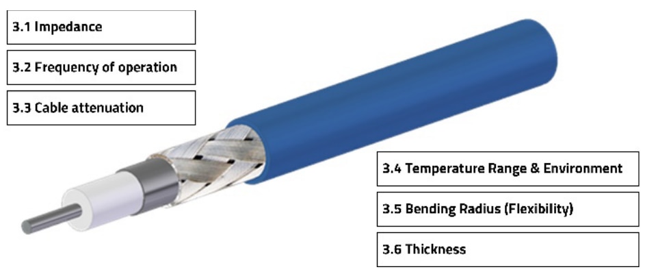
Figure 4: Six criteria for cable selection
3.1 Check impedance
The two main cable impedances on the market are 50 Ω and 75 Ω, Würth Elektronik cable assembly products are all 50 Ω. The application and device will determine cable impedance required.
3.2 Frequency of operation
It’s important to consider the signal frequency as each cable has different performance parameters. Higher frequency signals suffer from greater resistive loss due to skin effect which can result in greater attenuation. Cables are also limited to a cut off frequency due to their physical size in relation to the signal wave length.
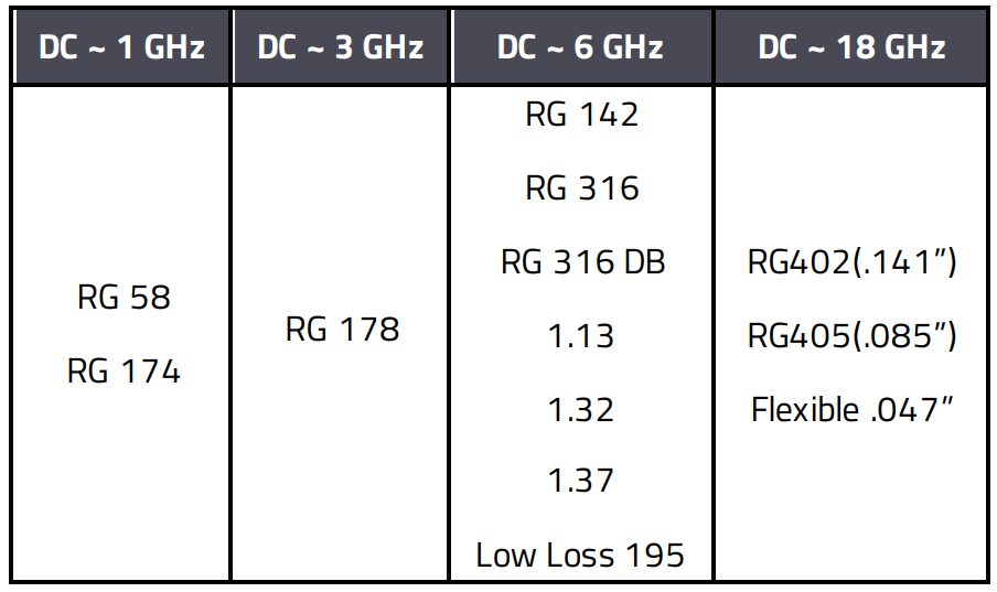
Table 2: Cable frequency range
Example:
Take a Wi-Fi application as an example. If the system only requires a 2.4 GHz channel, a RG178 cable could support it. If the system is running both 2.4 GHz and 5.8 GHz bands, it must use a higher rated cable from the DC~6 GHz category.
3.3 Cable attenuation
Cable attenuation represents the amount of signal loss over a specific distance which is given in units of dB/m. A more expensive low loss cable may prove to be a more economical solution than a cable with higher attenuation that requires an additional signal booster.
Example:
If one wishes to use the FM frequency of 108 MHz, there is RG58 and RG174 to select from. Comparing the attenuation at 1 GHz, RG58 is 0.56 dB/m and RG174 is 1.09 dB/m. Ideally, RG58 would be a good choice if only taking attenuation into consideration. However, other characteristics may need to be considered such as: cable bending radius, cable thickness, etc.
3.4 Temperature range & environment
Cables may be used in different environments depending on material used. Most cables with PE or PVC jackets can be used up to 80°C and cables with FEP jacket range up to 200°C. The jacket also provides environment protection.
- PVC is a robust and durable material widely used on economical cables.
- PE is advantageous against moisture, weather, and UV resistances. It’s ideal for outdoor applications.
- FEP has additional protection against oil and chemicals.
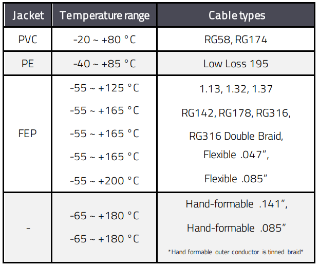
Table 3 : Cable temperature range
Example:
If a telecommunication system requires light weight and operates at higher frequency points, .085”, .047” and .141” cables would be a good product choice. Hand-formable cable with its outer conductor of tinned braid is often preferred for easy installation where it can be protected inside of a device. Flexible .047” and .085” equipped with a FEP cable jacket provides advanced protection against oil and chemicals. Specifications define these cables can reach up to +200°C. From a product assembly point of view, +165°C is more appropriate when it comes to soldering process.
3.5 Bending radius (flexibility)
The bend radius represents the sharpest bend the cable can withstand without potential damage and degradation of performance. Over-bending the cable damages its internal structure and will directly result in poorer electrical performance of an assembly. Cable bending radius does not have a direct result to cable thickness, there are a few influences according to cable structure:
- Center conductor structure (solid/stranded)
- Layers of shielding/ braid
- Material of cable jacket
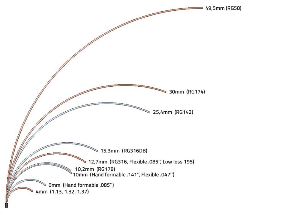
Figure 5: Cable bend radius
3.6 Thickness
Knowing the cable’s outer diameter is often helpful for cable installation.

Figure 6 : Cable outer diameter
Nominal cable outer diameter table:
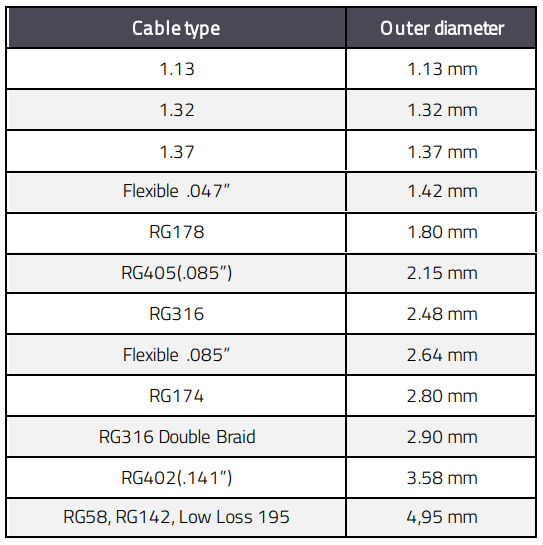
Table 4: Cable outer diameter
04. MANAGE A CUSTOMIZE CABLE ASSEMBLY
Würth Elektronik offers a ‘made to order’ cable assembly service which supports reduction of user’s assembly work load and manages the requirement of reliable signal transmission. Here is list of things to consider and the required information to get a cable assembly:
4.1 Check points of a complete assembly

Figure 7 : Nominal cable assembly
- Connector 1 and Connector 2: Check interface, orientation or ingress protection function.
- Heat Shrink Tube: Check specific length, color or customize text.
- Label: Apply with standard WE PN or customize content or special label.
- Length: Check definition of length.
Length Tolerance:
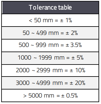
Table 5: Length tolerance
4.2 Check points for a strip end cable assembly

Figure 8 : Strip end cable & direct cut cable
The strip end could make assembly easier for user according the need:
- Stripping dimension A, B, C: Usually tolerance is specified.
- Direct Cut: User strip or perform assembly in other method.
- Tinned braid or Pig tail: Such assemblies allow user quickly make cable perform without a connector or proper shielding. Tinned braid avoids splay or damage during transportation and is easier for assembly.
- Tinned center conductor: Tinned stranded center conductor is helpful to prevent damage during transportation and makes it easier for assembly. An open expose end of an assembly should be aware the risk of crimping or vibration application.
05. IDENTIFY COAXIAL CABLE ATTENUATION & CHARACTERISTICS
5.1 Know Characteristics and Select
A quick method to select a cable type is through its nominal working frequency range. At Würth Elektronik, there are four ranges of frequencies for standard coaxial cable types: DC up to 1 GHz, 3 GHz, 6 GHz and 18 GHz as outlined in Table 2.
Example:
When selecting a cable assembly for FM radio, the working frequency is mainly about 800~900 MHz, the option could be: RG58, RG174 or RG178.
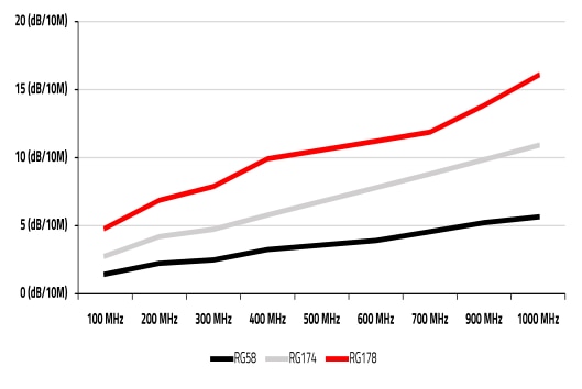
Figure 9: Cable attenuation overview
If user only selects the cable by attenuation specification, the ideal choice is RG58 which presents the best attenuation result.
However, there are other characteristics to consider in the selection:
- Cable thickness: RG58 (4.95mm) > RG174 (2.7mm) > RG178 (1.8mm)
- Cable bend radius (flexibility): RG58 > RG 174 > RG178
- Cable weight: RG58 > RG 174 > RG178
RG178 could be the ideal option based on it covering the frequency range (up to 3 GHz). However, its higher attenuation performance is related to its thickness. The advantage is its weight and FEP cable jacket.
5.2 Cable Attenuation and Cable Length
On the Würth Elektronik datasheet, we provide typical cable attenuation graphs to let the user easily calculate attenuation at different cable lengths. This helps the user quickly determine how a specific frequency point would perform when cable length changes, and one can match the cable routing need to other factors.
Example:
If one needs to know how 5.8 GHz attenuation changes between 3 feet and 5 feet lengths when using an assembly of SMA straight plug to SMA straight plug on RG316 double braid cable, here is the attenuation table and formula to support:
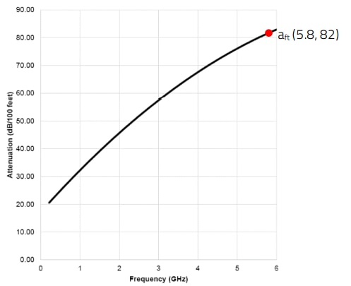
Figure 10 : Example of RG316DB with SMA Plug attenuation
Calculation formula for attenuation:

alx: attenuation at desired cable length
a100ft: length per 100 ft, (Value out of diagram)
100: factor in ft for normalization to 1 ft
lx: desired length ft: feet , 1
ft = 0,3048 m
Calculate attenuation of 3 feet at 5.8 GHz:

Calculate attenuation of 5 feet at 5.8 GHz:

In this example, the attenuation at 5.8 GHz of two extra feet is 1.64 dB. The attenuation difference gets larger related to:
- Higher working frequency point
- Length of cable
06. SUMMARY
Coaxial cables are widely used as transmission lines for radio frequency signals. The quality of a coaxial cable assembly is related to many production and assembly details of the product. However, to remember all details of coaxial cable types can be very complicated. After reading through these suggestions users should now understand what critical points to check when selecting a coaxial cable.
IMPORTANT NOTICE
The Application Note is based on our knowledge and experience of typical requirements concerning these areas. It serves as general guidance and should not be construed as a commitment for the suitability for customer applications by Würth Elektronik eiSos GmbH & Co. KG. The information in the Application Note is subject to change without notice. This document and parts thereof must not be reproduced or copied without written permission, and contents thereof must not be imparted to a third party nor be used for any unauthorized purpose. Würth Elektronik eiSos GmbH & Co. KG and its subsidiaries and affiliates (WE) are not liable for application assistance of any kind. Customers may use WE’s assistance and product recommendations for their applications and design. The responsibility for the applicability and use of WE Products in a particular customer design is always solely within the authority of the customer. Due to this fact it is up to the customer to evaluate and investigate, where appropriate, and decide whether the device with the specific product characteristics described in the product specification is valid and suitable for the respective customer application or not. The technical specifications are stated in the current data sheet of the products. Therefore the customers shall use the data sheets and are cautioned to verify that data sheets are current. The current data sheets can be downloaded at www.we-online.com. Customers shall strictly observe any product-specific notes, cautions and warnings. WE reserves the right to make corrections, modifications, enhancements, improvements, and other changes to its products and services. WE DOES NOT WARRANT OR REPRESENT THAT ANY LICENSE, EITHER EXPRESS OR IMPLIED, IS GRANTED UNDER ANY PATENT RIGHT, COPYRIGHT, MASK WORK RIGHT, OR OTHER INTELLECTUAL PROPERTY RIGHT RELATING TO ANY COMBINATION, MACHINE, OR PROCESS IN WHICH WE PRODUCTS OR SERVICES ARE USED. INFORMATION PUBLISHED BY WE REGARDING THIRD-PARTY PRODUCTS OR SERVICES DOES NOT CONSTITUTE A LICENSE FROM WE TO USE SUCH PRODUCTS OR SERVICES OR A WARRANTY OR ENDORSEMENT THEREOF. WE products are not authorized for use in safety-critical applications, or where a failure of the product is reasonably expected to cause severe personal injury or death. Moreover, WE products are neither designed nor intended for use in areas such as military, aerospace, aviation, nuclear control, submarine, transportation (automotive control, train control, ship control), transportation signal, disaster prevention, medical, public information network etc. Customers shall inform WE about the intent of such usage before design-in stage. In certain customer applications requiring a very high level of safety and in which the malfunction or failure of an electronic component could endanger human life or health, customers must ensure that they have all necessary expertise in the safety and regulatory ramifications of their applications. Customers acknowledge and agree that they are solely responsible for all legal, regulatory and safety-related requirements concerning their products and any use of WE products in such safety-critical applications, notwithstanding any applications-related information or support that may be provided by WE. CUSTOMERS SHALL INDEMNIFY WE AGAINST ANY DAMAGES ARISING OUT OF THE USE OF WE PRODUCTS IN SUCH SAFETYCRITICAL APPLICATIONS.
DIRECT LINKS
ANE16: Coaxial cables and cable assemblies
USEFUL LINKS:
Application Notes : https://we-online.com/en/support/knowledge/application-notes
Services: https://we-online.com/en/products/components/service
Contact : https://we-online.com/en/support/contact
CONTACT INFORMATION
Würth Elektronik eiSos GmbH & Co. KG
Max-Eyth-Str. 1, 74638 Waldenburg, Germany
Tel.: +49 (0) 7942 / 945 – 0
Email: appnotes@we-online.de

