


Application Notes
M12 A-Coded Circular Connectors Use Cases
ANE019 by Caroline Poulard & Baptiste Bouix
01. INTRODUCTION
M-12 Circular Connectors are sturdy, mechanically and environmentally resistant components fit for industrial and outdoor uses. Therefore, a sizable number of field bus protocols use them as electrical and mechanical interface between end-devices, as part of their physical layer (as per the OSI model formalism).
M12 circular connectors exist in several codings, for example A, B, D or X among others. However, in this application note, we are going to focus on the use cases of the M12 A-Coded from Würth Elektronik product range in physical layers. The focus will be on industry-oriented interconnect.
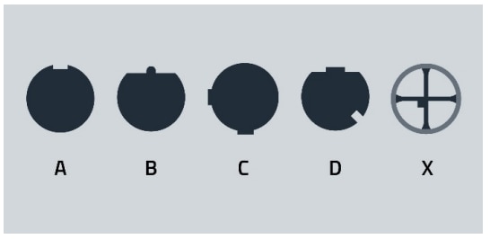
Figure 1 - M12 coding overview
02. M12 A-CODED IN ETHERNET-OVER-TWISTED-PAIR PHYSICAL LAYER
Ethernet over Twisted Pair (EOTP) is one of the most important physical layers for Ethernet and a sizeable amount of industrial protocols work on the Ethernet data link and physical layers standards. However, the M12 are not the native connectors upon which the EOTP interface has been developed.
The Ethernet standard serves as a basis for the EtherCAT, EtherNet/IP, PROFINET, CC-Link IE, POWERLINK, SERCOS III and Modbus TCP protocols.
2.1 10BASE-T
The 8-pin M12 A-Coded circular connector can be used as a replacement for the RJ45 in an ANSI/TIA-568 Category 3 Cabling system, used for the 10 Mb/s 10BASE-T Ethernet interface. The Cat 3 cable is made of four 100 ohm differential impedance twisted pairs.
In this case, when wiring a RJ45 (8P8C Modular Plug) to a M12 A-Coded circular connector, the assignment in Figure 2 is advised.
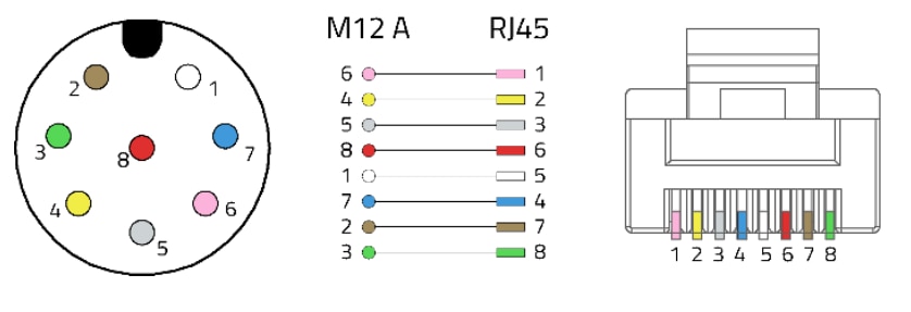
Figure 2 - 10BASE-T M12 to RJ45 pin assignment
When wiring a M12 A-Coded circular connector to a M12 ACoded circular connector, a pin assignment as shown in Figure 3 is recommended.
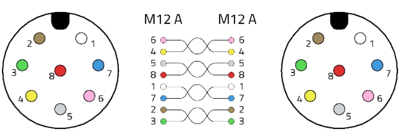
Figure 3 - 10BASE-T M12 to M12 pin assignment
These pin assignments minimize the delay skew between contacts of the same pair. This wiring is a widespread configuration for A-Coded M12 EOTP cabling. While 10BASET only uses 2 pairs for signal transmission, it is not advised to only have 2 pairs in the cable nor to use a 4-pin A-Coded circular connector as it may cause confusion with other widespread uses. For 2-pair EOTP cabling with M12, a D-coded connector is recommended.
2.2 100BASE-T
For 100 Mb/s EOTP standards, D-Coded circular connectors will generally be used with 2-pair cables. However, it is possible to make an interface using an A-Coded circular connector by following the same pin assignment as for the 10-BASE-T.
When designing such an interface, the signal integrity has to be taken into consideration. The entire cable assembly, including connectors, have to fit within the category of the cable assembly as per ANSI/TIA-568. Each of the male/female connector pair and the cable itself will have losses and crosstalk budgets not to exceed. It is advised to test the S-parameters of such an interface, depending mostly of the cable category and cable length.
2.3 Higher BASE-T
For higher data rate EOTP standards, X-Coded circular connectors will generally be used with 4-pair cables. However, it is possible to make an interface using a M12 ACoded circular connector by following the same pin assignment as for the 10-BASE-T as with 100BASE-T, and with the same signal integrity considerations. Such an interface will generally need to have a much shorter cable length.
Signal integrity performances of M12 A-Coded circular connectors and cable assemblies will be the subject of a further Application Note.
03. M12 A-CODED IN IO-LINK PHYSICAL LAYER
IO-Link is a standardized digital data transfer and power supply protocol between a programmable hub and sensors or actuators peripherals.
IO-Link describes the electromechanical interface as 4 or 5- pin A-Coded M12 circular connectors linked with a 3 or 5-wire 20 meter cables. The port associated with 3-wire cable will be called “Class A” and the port associated with 5-wire cable will be called “Class B”.
The Master hub ports will always be 5-pin M12 A-Coded receptacles. On the Device port, it can be a captive cable, or a M12 A-Coded 4 or 5-pin depending on the wanted crosscompatibility.
Let us have a view on the needed pinouts for different Class A and Class B connections.
3.1 Class A, 3-wire cable
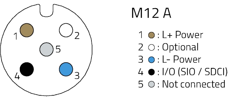
Figure 4 - Class A port on the Master side will be a 5-pin M12 A-Coded receptacle
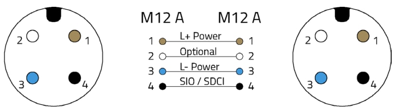
Figure 5 - Class A ports on the cable side will be 4-pin M12 A-Coded plugs

Figure 6 - Class A port on the Device side will be a 4- or 5-pin M12 A-Coded receptacle
3.2 Class B, 5-wire cable
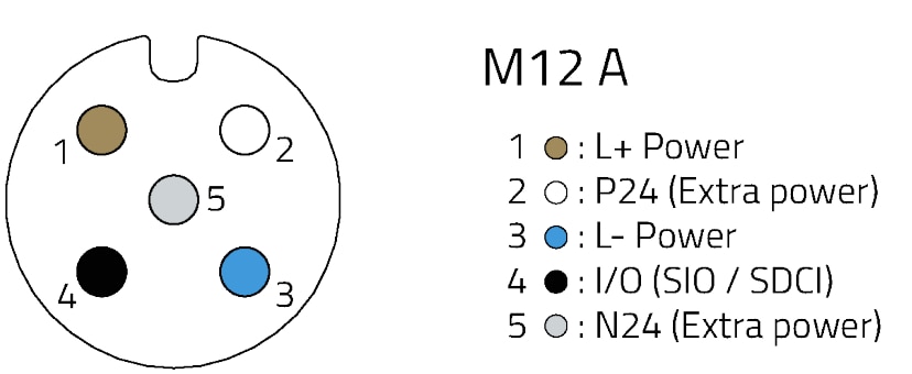
Figure 7 - Class B ports and cables on Hub and Device sides will be 5-pin M12 A-Coded receptacles
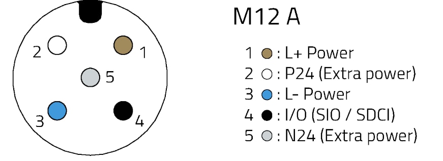
Figure 8 - IO-Link Class B2 plug
04. M12 A-CODED IN USB 2.0 PHYSICAL LAYER
The Universal Serial Bus is one of the most common connectivity layers on the market. USB in its 2.0 revision can be used as a power supply and high-speed data bus. M12 A-Coded circular connectors can be used to offer a mechanically sturdier ending to a USB 2.0 cable.
USB 2.0 cable assemblies use 2 power pins for VBUS and GND and a 90 ohm differential impedance twisted pair for the USB signal. The 4-pin M12 A-coded circular connector can be used to transmit USB signaling.
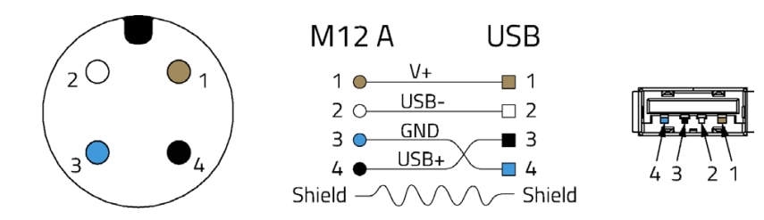
Figure 9 - M12 A-Coded plug to USB 2.0 pinout
If the termination is a mini or micro USB connector, the ID pin can be wired as such on a 5-pin M12 A-coded circular connector. Connector shielding can be connected to the cable shielding braid.
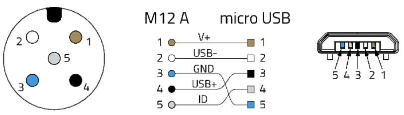
Figure 10 - M12 A-Coded plug to micro USB 2.0 connector
USB cables generally have lengths of 1 to 3 m. Connector shielding can be connected to the cable shielding braid.
05. M12 A-CODED IN IN INDUSTRIAL BUS SYSEMS
5.1 M12 A-Coded in CANbus Physical Layer
The CANopen and DeviceNET use the CANbus layer to operate. While it was initially designed to use a small formfactor D-SUB connector, a popular interface for the CANbus is the 5-pin M12 A-coded circular connector.
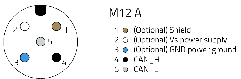
Figure 11 - CANbus pinout at 5-pin M12 A-coded plug
Only the CAN_H and CAN_L signal pair wired to the pins 4 and 5 are mandatory, however this configuration lets you supply power to the device. The wiring for the signal pair should be a 120 ohm twisted wires pair in 40-meter cables.
5.2 M12 A-Coded in RS-485 Physical Layer
The RS-485 physical layer is widely used for the Modbus, OSDP, SSCP, SCSI-2, SCSI-3, Profibus, Nanoréseau, DMX 512 and AES 3 industrial protocols. 5-pin or 4-pin shielded A-Coded are used for RS-485. The wiring will be mostly dependent on the needed power supply but will always include at least the balanced TxD/RxD pair in position 2 and 4 to minimize the delay skew.
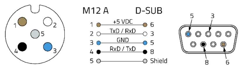
Figure 12 - RS-485 pinout at M12 A-coded receptacle
Please note that the M12 A-Coded circular connectors are used for half-duplex RS-485. For full-duplex RS-485, M12 B-coded circular connectors are generally used.
The cable length will directly affect the data rate. For a 1200 meter cable, it will be limited to 100 Kb/s, while for 12 m and below, it will be possible to transmit 35 Mb/s. The signal pair impedance must be 120 ohm.
5.3 M12 A-Coded in Profibus Physical Layer
M12 A-Coded circular connectors are used as power supply connectors for Profibus peripherals.
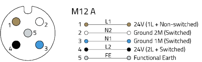
Figure 13 - PROFIBUS Pin assignment for 5-pin M12 A-Coded receptacle
M12 B-Coded circular connectors are used for Profibus signal transmission.
5.4 M12 A-Coded in RS-422, RS-423 and RS-232 Physical Layer
8-pin, 5-pin or 4-pin M12 A-Coded circular connectors can be used for RS-422, RS-423 or RS-232. The wiring will be mostly dependent on the needed signal, power supply and ground return needed. There is no set pinout for these.
For RS-422, at least one pair of wires will have to be balanced. The conductors will need to have the same length, and thus only some pin combinations will be possible. In the 4 or 5- pin M12 A-Coded circular connectors, only the 2 and 4 contacts will have the same length. In the 8-pin M12 A-Coded connectors, the pairs are pins 1-2, 3-7 and 4-6. Therefore, it is possible to have one differential pair in a 4 or 5-pin and 3 pairs in 8-pin M12 A-Coded circular connectors.
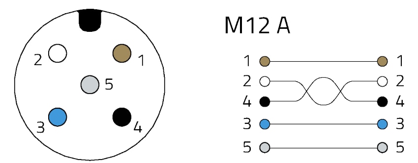
Figure 14 - RS-422 / RS-423 pinout one balanced pair (plug)
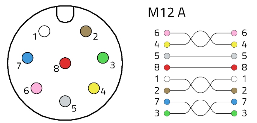
Figure 15 - RS-232 pinout with 3 balanced pairs (receptacle)
06. CONCLUSION
M12 A connectors are quite versatile and can be used with several communication protocols and fieldbuses, they are not bound to a single protocol. Moreover, they are able to work in harsh environments (vibration, dust, water), thanks to their high IP-rating & their steady screw-locking. Those two features allow these M12 A connectors to be a must in automation industry especially for all sensors, actuators connections.
For higher-rated Ethernet protocols, other codings such as D or X can be used. (This will be expanded in a later appnote.)
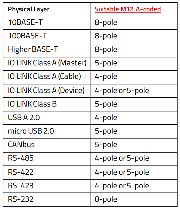
07. PHYSICAL LAYER – M12 A OVERVIEW
IMPORTANT NOTICE
The Application Note is based on our knowledge and experience of typical requirements concerning these areas. It serves as general guidance and should not be construed as a commitment for the suitability for customer applications by Würth Elektronik eiSos GmbH & Co. KG. The information in the Application Note is subject to change without notice. This document and parts thereof must not be reproduced or copied without written permission, and contents thereof must not be imparted to a third party nor be used for any unauthorized purpose. Würth Elektronik eiSos GmbH & Co. KG and its subsidiaries and affiliates (WE) are not liable for application assistance of any kind. Customers may use WE’s assistance and product recommendations for their applications and design. The responsibility for the applicability and use of WE Products in a particular customer design is always solely within the authority of the customer. Due to this fact it is up to the customer to evaluate and investigate, where appropriate, and decide whether the device with the specific product characteristics described in the product specification is valid and suitable for the respective customer application or not. The technical specifications are stated in the current data sheet of the products. Therefore the customers shall use the data sheets and are cautioned to verify that data sheets are current. The current data sheets can be downloaded at www.we-online.com. Customers shall strictly observe any product-specific notes, cautions and warnings. WE reserves the right to make corrections, modifications, enhancements, improvements, and other changes to its products and services. WE DOES NOT WARRANT OR REPRESENT THAT ANY LICENSE, EITHER EXPRESS OR IMPLIED, IS GRANTED UNDER ANY PATENT RIGHT, COPYRIGHT, MASK WORK RIGHT, OR OTHER INTELLECTUAL PROPERTY RIGHT RELATING TO ANY COMBINATION, MACHINE, OR PROCESS IN WHICH WE PRODUCTS OR SERVICES ARE USED. INFORMATION PUBLISHED BY WE REGARDING THIRD-PARTY PRODUCTS OR SERVICES DOES NOT CONSTITUTE A LICENSE FROM WE TO USE SUCH PRODUCTS OR SERVICES OR A WARRANTY OR ENDORSEMENT THEREOF. WE products are not authorized for use in safety-critical applications, or where a failure of the product is reasonably expected to cause severe personal injury or death. Moreover, WE products are neither designed nor intended for use in areas such as military, aerospace, aviation, nuclear control, submarine, transportation (automotive control, train control, ship control), transportation signal, disaster prevention, medical, public information network etc. Customers shall inform WE about the intent of such usage before design-in stage. In certain customer applications requiring a very high level of safety and in which the malfunction or failure of an electronic component could endanger human life or health, customers must ensure that they have all necessary expertise in the safety and regulatory ramifications of their applications. Customers acknowledge and agree that they are solely responsible for all legal, regulatory and safety-related requirements concerning their products and any use of WE products in such safety-critical applications, notwithstanding any applications-related information or support that may be provided by WE. CUSTOMERS SHALL INDEMNIFY WE AGAINST ANY DAMAGES ARISING OUT OF THE USE OF WE PRODUCTS IN SUCH SAFETYCRITICAL APPLICATIONS
DIRECT LINK
ANE019 | M12A-Coded Circular Conectors
USEFUL LINKS:
Application Notes : https://we-online.com/en/support/knowledge/application-notes
Services: https://we-online.com/en/products/components/service
Contact : https://we-online.com/en/support/contact
CONTACT INFORMATION
Würth Elektronik eiSos GmbH & Co. KG
Max-Eyth-Str. 1, 74638 Waldenburg, Germany
Tel.: +49 (0) 7942 / 945 – 0
Email: appnotes@we-online.de
