

.jpg-1440x400x2.jpg?sv=2016-05-31&sr=b&sig=SzkKTBYqUh%2F6%2FFD0b72JXCxRIPRI0bGq2cL8VFfWUy4%3D&se=2026-03-31T23%3A59%3A59Z&sp=r&_=JZzprw0cWdPfS+IfTjd74g==)
Application Note
Coaxial Connectors Electrical Performance Indicators
ANE022 by Olan Tsai
1. INTRODUCTION AND THEORETICAL BACKGROUND
RF connectors are essential components in a variety of electronic devices and communication systems. They are designed to transmit high-frequency signals, such as radio frequency (RF) and microwave signals, with minimal signal loss and high reliability. The coaxial structure, consisting of an inner conductor, insulation layer, and outer conductor, effectively prevents electromagnetic interference and signal degradation.
Understanding the electrical performance indicators of RF connectors, including their maximum voltage, current, and power ratings, is essential. These parameters are critical for ensuring the safe and reliable operation of the connectors, especially in high-power scenarios.
This note will provide typical values for the maximum voltage, current, and power handling capabilities of various coaxial connectors, ensuring users can select the appropriate connector for their needs.
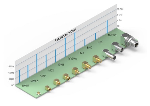
Figure 1: Coaxial connector frequency range.
1.1 Voltage Handling
The maximum voltage that a coaxial connector can handle is defined by its dielectric withstanding voltage, which is the highest voltage the connector's insulation material can endure without breaking down. Determined through standardized testing, this voltage ensures safe operation under specified conditions.
Dielectric Withstanding Voltage
This parameter is cornerstone of voltage handling capability, representing the maximum voltage the insulation material can withstand without electrical breakdown.
Common insulation-materials used for RF connectors include PTFE, POM, and LCP, among others. The choice of material significantly impacts the dielectric withstanding voltage.
The physical design and construction of the connector, including the spacing and geometry of the conductors and insulators, play a significant role in voltage handling. Additionally, environmental factors such as temperature, humidity, and exposure to contaminants can impact the voltage handling capacity of a connector. Proper design and material selection are essential to optimize voltage handling in specific application environments.
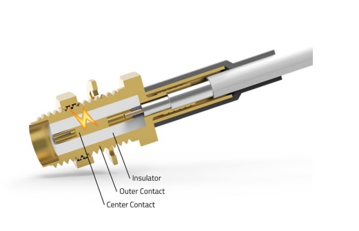
Figure 2: Coaxial connector cross-section with a lightning symbol indicating the dielectric withstanding voltage test.High voltage is applied between the inner and outer conductors to ensure the insulation can withstand voltage without breakdown
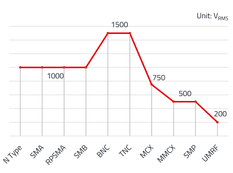
Figure 3: Connector types of maximum voltage. Different product designs may have different maximum voltage ratings, so please refer to the datasheet for specific values.
1.2 Working Voltage
The working voltage, also known as the rated voltage, is the maximum continuous voltage that a coaxial connector can handle during normal operation without degradation or risk of failure. It is typically lower than the dielectric withstanding voltage to provide a safety margin. The working voltage is determined based on factors such as the dielectric material properties, connector design, and the operating environment. Ensuring that the working voltage is not exceeded is crucial for the long-term reliability and safety of the connector.
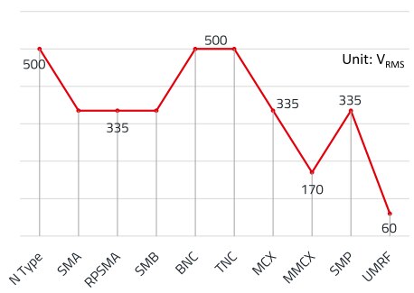
Figure 4: Connector types of typical working voltage.
1.3 Current Handling
The current handling capacity of a coaxial connector is limited by the thermal properties of its materials and design. Excessive current can cause overheating, leading to material degradation and failure. The connector's inner conductor and contact resistance are critical factors affecting its current handling capability.
When defining the maximum current that a coaxial connector can handle, it is essential to consider not only the voltage handling capabilities but also the maximum power rating. The relationship between voltage, current, and power is critical in determining the safe operating limits for the connector.
The maximum current is calculated using the formula:
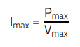 (1)
(1)
The limitation of current ensures that the connector operates within its thermal and electrical limits, preventing overheating and potential failure.
1.4 Power Handling
The power handling capacity of a coaxial connector is a critical parameter, especially in high-frequency applications. This capacity is determined by the connector's ability to handle power without compromising performance or safety.
To accurately determine the power handling capacity of a coaxial connector across different frequencies, we need to consider the influence of insertion loss. Insertion loss, typically measured in decibels (dB), represents the loss of signal power resulting from the insertion of a connector in a transmission line. This loss increases with frequency, thereby reducing the effective power handling capacity of the connector.
The general formula to estimate the power handling capacity at any given frequency f is:
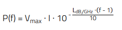 (2)
(2)
Where:
- Vmax: Maximum dielectric withstanding voltage of the connector.
- I: Current through the connector.
- LdB/GHz: Insertion loss per GHz.
- f: Operating frequency in GHz.
The formula takes into account the transmission losses () by reducing the power by a factor of 10-( ()/10). The product max ⋅ corresponds to the total power without taking losses into account. 10-( ()/10) describes the remaining power after the frequency-dependent attenuationHowever, this formula does not directly consider the thermal effects caused by dielectric and conductor losses at high frequencies. The heat generated at high frequencies significantly impacts the power handling capacity of the connector. Particularly, as the frequency increases, conductor and dielectric losses increase, leading to a rise in temperature, which affects the performance and reliability of the connector. Therefore, calculating the power handling capacity of a connector at high frequencies requires considering not only insertion loss but also thermal effects.
To more accurately calculate the power handling capacity of a connector at high frequencies, the following factors need to be considered:
- Conductor Loss: At high frequencies, current concentrates on the surface of the conductor due to the skin effect, increasing the conductor's resistance and loss.
- Dielectric Loss: At high frequencies, the dissipation factor of the dielectric material increases, leading to more energy being converted into heat.
- Thermal Management: The thermal conductivity and heat dissipation capability of the connector determine whether it can maintain a low temperature under high power.
A more complex and precise calculation method requires simulating thermal effects under high-frequency conditions, which typically involves using electromagnetic field analysis and thermal analysis.
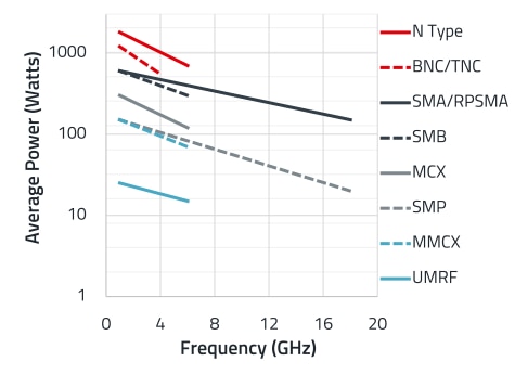
Figure 5: The average power handling of coaxial connectors, with consideration for high-frequency thermal effects. It's important to note that the values of power handling may vary depending on the design of the product and the operating environment.
2. CONCLUSION
When selecting coaxial connectors, it’s crucial to consider their voltage, current, and power handling capabilities based on operating frequency and use. Properly chosen connectors offer these benefits:
- Stable Operation: Operating within specified limits enhances stability and reduces failure risks.
- High-Quality Signal: Correct voltage and current handling preserve signal integrity and reduces distortion.
- Extended Lifespan: Avoiding overload and thermal damage helps connectors last longer.
- Increased Reliability: Lower risk of breakdowns and overheating improves overall system reliability.
- Reduced Maintenance: Appropriate connectors reduce the need for frequent replacements, saving on costs.
- Enhanced Performance: Ensures stable performance in high-frequency applications.
- Safety: Following power guidelines prevents overloads and short circuits, ensuring safety for both systems and operators.
In addition to selecting connectors with appropriate electrical characteristics, the durability of their mechanical structure— especially for connecting and disconnecting—can also impact their electrical performance. Key mechanical factors to consider include:
- Durability and Wear: Frequent mating and un-mating can wear down the connector’s plating, which may increase contact resistance and, in turn, degrade electrical performance.
- Connector Damage or Deformation: Mechanical wear or damage can alter the connector’s RF characteristics and compromise its ability to meet original safety and dielectric withstand ratings.
Regular inspections, maintenance, and timely replacement of connectors are therefore essential for ensuring continued electrical safety and performance of the product.