Application Note
15W Multi Output Offline Flyback Transformer
Design Considerations Taken to Achieve over 86% Efficiency for Industrial Appliance Applications
ANP094 BY SUCHETHAN SWAROOP VAIDYANATH, WÜRTH ELEKTRONIK AND JOHN DOROSA, TEXAS INSTRUMENTS
1 Introduction
Next generation battery chargers used in industrial appliance applications such as power tools often require isolated AC/DC power supplies with high efficiency, low profile, low standby power and small form factor along with multiple outputs. The UCC28711 flyback power supply controller provides isolated outputs without the use of an optical coupler. This translates into fewer number of components on the board. This controller processes information from the auxiliary flyback winding for precise control of output voltage and current. Quasi resonant mode with valley switching reduces switching losses. The primary side MOSFET turns on during the first valley at maximum load. The UCC28711 has a maximum switching frequency of 100 kHz and always maintains control of the primary peak current in the transformer. Texas Instrument’s reference design PMP21927 takes a universal VAC input and creates three isolated 15 V outputs. The main output can be loaded up to 1 A and achieves over 86% efficiency. The other two isolated 15 V outputs can be loaded to 50 mA each. Using primary side regulation usually gives +/-5% regulation accuracy related to the output voltage and normally it is avoided when multiple outputs are involved. In this design, the low current outputs have LDO linear regulators to keep the voltages within 1% regardless of cross-loading conditions. The transformer is a principal component in such designs. Building a transformer is often an iterative process with many incremental changes that can affect the overall efficiency. In this application note, we will focus on the flyback transformer design with multi-isolated outputs used in PMP21927 and discuss the many design considerations taken to achieve high efficiency while maintaining a low profile part for power tool applications.
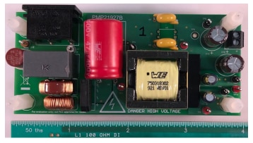
Figure 1: Top view of PMP21927 15W multi output offline flyback reference design board
2 Design parameters of 15 W QR offline flyback transformer with three outputs
- Input voltage range : 85-265 VAC
- Output 1: 15 V / 1 A
- Output 2 and Output 3: 15 V / 50 mA after regulation (16.7 V before regulation)
- Auxiliary (bias) output: 18 V / 20 mA
- Frequency of operation: 70 to 80 kHz
- Safety standard : UL60950-1 with reinforced insulation

Figure 2: 750318302 transformer windings
The maximum available duty cycle (Dmax) is based on discontinuous conduction mode (DCM), resonant time (tR), target switching frequency at max load (Fmax) and demagnetizing duty cycle (Dmagcc). Demagnetizing duty cycle is the secondary diode conduction duty cycle during constant current operation and it is set internally by the UCC2871x family to 0.425. All equations listed in sections 2 through 8 are referenced from TI’s UCC2871x controller family datasheet.
The equation for maximum duty cycle is as follows:


Figure 3: 15 W multi-output offline flyback reference design schematic
3 Primary to secondary turns ratio calculation
Since we have three outputs, we will use the output with the highest power of 15 V / 1 A as a starting point to calculate the turn’s ratios. Note that this can be an iterative process since multiple outputs are involved. The maximum primary to secondary turns ratio, NPS1 is calculated at the maximum frequency at full load, along with estimated DCM resonant time, minimum input capacitor bulk voltage (Vbulkmin), regulated output voltage (Vocv), secondary rectifier forward voltage drop at near zero current (Vf) and target cable compensation voltage at the output terminals (Vocbc).

We will round down NPS1max = 6.
4 Other secondary windings turns ratio calculation
The turns ratio of the additional secondary windings is based on the regulated secondary and can be calculated using a simple ratio.

The turns ratio of secondary 3 is same as secondary 2 with the actual turns rounded up to the next full turn.
5 Auxiliary winding to secondary winding turns ratio calculation
The bias supply from the auxiliary winding is used for voltage sensing and powering the IC. Hence, the winding is kept on the same side of the bobbin as the primary winding. The auxiliary winding also operates at the same time as the secondary windings. The turns ratio (NAS1) is calculated using the bias supply undervoltage lockout (UVLO) voltage (VDDoff = 7.35 V) which is a device parameter, auxiliary rectifying diode forward voltage drop (Vfa = 0.7 V), minimum desired output voltage during constant current mode (VOCC = 6.09 V) and the forward voltage drop of output rectifying diode (Vf = 0.5 V). There is additional energy supplied to VDD from the transformer leakage inductance which allows a lower turns ratio to be used in many designs.

6 Current sense resistor calculation
The transformer turns ratio and UCC2871x constant-current regulating voltage (Vccr) determine the current sense resistor for a target current (Iocc = 1.3 A). As not all of the energy stored in the transformer is transferred to the secondary, the transformer efficiency term is included. At the design phase, we assume 3.5 % leakage inductance, 5% core and winding losses, and 1.5 % bias power losses, for an overall transformer efficiency factor of ƞ = 0.9 or 90 %.

We will select a current sense resistor with RCS = 0.75 Ω.
7 Primary and secondary peak currents calculation
Peak currents are important in calculating the required primary inductance needed in the transformer. Primary peak current is simply the maximum current sense threshold at the controller (Vcstmax) divided by the current sense resistance (Rcs).

The secondary peak current (Ispmax) is the primary peak current (Ippmax) multiplied by turns ratio (NPS1) of the transformer.

where NPS2 = NPS1/NS2S1 = 6/1.11 = 5.4 and LP= 450 µH, calculated in the next section.
PO2=PO3=16.7 V ⋅ 50 mA = 0.835 W

8 Primary inductance calculation
The primary inductance of the transformer (Lp) is calculated using the standard energy storage equation for inductors (E = 1 2 L ⋅I 2 ). The parameters required are primary peak current (Ipp), maximum switching frequency (Fmax), total power (Pout) and transformer efficiency (ƞ).
Pout = (15 V ⋅ 1 A) + 2 (16.7 V ⋅ 50 mA) + (18 V ⋅ 20 mA)
Pout = 17.03 W

We shall select LP = 450 µH considering +/-10 % of tolerance.
9 Primary and secondary rms currents calculation
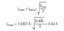
The primary and secondary rms currents are important to find the right wire sizes in the transformer. Primary rms current (Irmspri) is dependent on peak current (Ipp) and maximum duty cycle (Dmax).
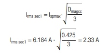
The equation for secondary rms current (Irms sec) is dependent on secondary peak current (Ispmax) and demagnetizing duty cycle (Dmagcc).
The rms currents on secondary 2 and secondary 3 windings can be calculated using these equations:

IS2 and IS3 are the maximum output DC currents and DoffS2 is the estimated duty cycle of the off time for the secondary 2 and 3 windings.

As we know the peak current and duty cycle, we can calculate the total rms current for the second and third windings.

10 Selection of the core and bobbin
For power applications below 500 kHz, Manganese-Zinc (Mn-Zn) ferrite material is preferred for cores as it has good performance with permeability (μr) from 2000 to 2500. TP4A core material is used in this design. Its saturation flux density (Bsat) is 390 mT at 100 °C. There are many core shapes available such as EE, EFD, EP, RM, PQ, ETD etc. The following parameters need to be taken into consideration while choosing the core and the bobbin:
a. Volume of the core needed
b. Size constraints such as low profile or footprint
c. Safety standards needed to be met
d. Insulation requirements (functional or reinforced)
e. Power that the core can handle at given frequency
f. Through hole or surface mount
g. Vertical or horizontal package
h. Number of pins needed on the bobbin
Calculating total input power Pin

We shall use the below equation to determine the effective volume of the core (Ve) needed. This equation is derived from the book: “Switching Power Supplies A-Z” by Sanjaya Maniktala.

Relative permeability (µr) is set to 2000. The maximum flux density (Bsat) is set to 300 mT to provide margin. One of the most important considerations in flyback transformer design is not to saturate the transformer. The core air gap factor (z), ALnogap/ALgapped is set to 10 and current ripple ratio (r), ∆I/I is set to 0.4.

From Würth Elektronik’s Custom Capabilities Catalog, the core volume of EFD25 package is 3.3 cm3 . The core volume of EFD20 package is 1.46 cm3 . Hence, we will choose EFD25 through whole package as it meets the core volume criteria of 2.37 cm3 and other requirements such as low profile height, an extended rail to meet the safety standards and 12 pins needed for multiple outputs.
11 Transformer wire sizes and construction
Based on thermal considerations, we choose the current density (J) to be 10 A/mm2 as mentioned in the book: “Optimal Design of Switching Power Supply” by Zhanyou Sha et al. The wire sizes are selected as below:

with equivalent minimum diameter of 0.23 mm for primary windings.

with equivalent minimum diameter of 0.54 mm for secondary windings. We need to choose the wire diameter to be less than twice of the skin effect depth for proper utilization of copper. The skin depth at 100 °C in millimeters can be calculated as follows:

The wire diameter should be less than twice the skin depth or 0.538 mm. Taking all of these parameters into consideration, 0.32 mm diameter wire (28 AWG) is chosen for primary and auxiliary windings. 0.53 mm diameter wire (23.5 AWG) is chosen for secondary windings. Thicker wire is preferred as it provides lower resistance. For the low current secondaries (2,3) 0.10 mm diameter wire (38 AWG) is chosen.
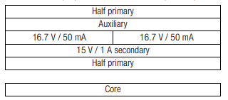
Figure 4: 750318302 construction diagram
Since there are more turns on the primary side, the primary is split to get better coupling and decrease overall leakage inductance. Half the primary winding is wound first, followed by the 15 V / 1 A secondary winding and both 16.7 V / 50 mA secondary windings. The auxiliary winding is wound next and finally the other half primary. There are layers of tape separating each winding. Triple insulated wire is used on the three secondary windings and standard magnet wire is used on the primary and auxiliary windings. This is done for two reasons. First, to keep the costs low as TIW wire is more expensive than magnet wire and there are fewer turns on the secondary windings. The second reason is to reduce the overall fill rate. The creepage and clearance distances are met as defined in UL60950-1 for reinforced insulation at a working voltage of 265 Vrms, overvoltage category II and a pollution degree 2 environment. Varnish is used to secure the core and windings in place and prevent ingression of moisture in the transformer. It also improves the thermal conductivity by aiding in transfer of heat from windings to free air and helps in sustaining dielectric capabilities as well.
12 Estimate losses
Core loss can be estimated using figure 5. Since this application uses a uni-polar waveform, and the chart in figure 5 is applicable to bi-polar waveforms with Bmax as peak to peak, we must divide the magnetic flux density in half to use the charts. In section 11 we chose a maximum magnetic flux density of 300 mT for the core. Dividing this in half gives 150 mT. Using the 100 kHz curve from figure 5, at 150 mT there is an approximate core loss per volume of 150 mW/cm3 (Note: mW/cm3 is the same as kW/m3 scaled by 10-6 ). Multiplying this value with the core volume of EFD25 package, 3.306 cm3 , gives us the approximate core loss.
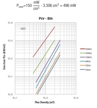
Figure 5: Flux density vs Core loss for TP4A material. Note that core loss units can be scaled by 10-6 to give mW/cm3
Simple copper loss can be estimated using I2 rms ∙ DCR. The rms currents are calculated in section 10. The DCR values are calculated from the average turn length and the wire resistance.
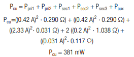
Total transformer loss = Pcore + Pcu = 887 mW
Transformer efficiency can be calculated as:

13 Temperature rise
A simple and fast estimate of temperature rise can be made by looking up the Rth of the core which represents the temperature rise for one watt of losses. For the EFD25 core, Rth = 30 K/W. Multiplying by the total losses gives the temperature rise above ambient.

14 Testing and efficiency graphs
The overall board efficiency was measured by loading the main 15 V output. The other two 15 V outputs were loaded to 50 mA and kept in regulation by the LDOs.
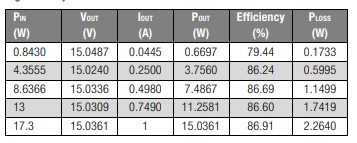
Table 1: Efficiency data for 120 VAC input
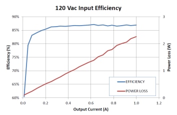
Figure 6: Total board efficiency graph with 120 VAC input
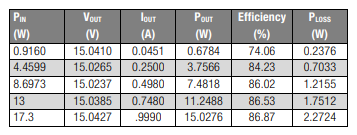
Table 2: Efficiency data for 230 VAC input
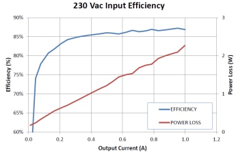
Figure 7: Total board efficiency graph with 230 VAC input
15 Conclusion
We had initially assumed 90% as the efficiency of our transformer during our design calculations considering 3.5 % leakage inductance losses, 5 % core and winding losses and 1.5 % bias power losses. We have calculated 5.15 % of loss from core and DC winding losses (estimated 6.5 % from all core and winding losses, including AC winding losses, which we didn’t calculate). Going with 90 % transformer efficiency during design phase for calculations for a three output flyback transformer is a very good estimate. AC losses and bobbin fill factor should be taken into consideration as well. As mentioned earlier, building a flyback transformer is an iterative process but these above guidelines should lessen the number of iterations and get us an optimum solution in about two revisions. On a system level, this 15 W multi-output, offline flyback design achieved over 86% efficiency, taking switching losses and other component losses into consideration.
A. Appendix
A.1. References
- Brander, T., Gerfer, A., Rall, B., Zenkner, H., Trilogy of Magnetics, 5th ed., Waldenburg, 2018
- PMP21927 : http://www.ti.com/tool/PMP21927
- UCC28710 datasheet : http://www.ti.com/lit/ds/symlink/ucc28710.pdf
- Würth Elektronik, Custom Capabilities Catalog
- Maniktala, S., Switching Power Supplies A-Z, 2nd ed., Oxford, Newnes, 2012
- Sha, Z. et al, Optimal design of switching power supply, Singapore, Wiley, 2015
IMPORTANT NOTICE
The Application Note is based on our knowledge and experience of typical requirements concerning these areas. It serves as general guidance and should not be construed as a commitment for the suitability for customer applications by Würth Elektronik eiSos GmbH & Co. KG. The information in the Application Note is subject to change without notice. This document and parts thereof must not be reproduced or copied without written permission, and contents thereof must not be imparted to a third party nor be used for any unauthorized purpose. Würth Elektronik eiSos GmbH & Co. KG and its subsidiaries and affiliates (WE) are not liable for application assistance of any kind. Customers may use WE’s assistance and product recommendations for their applications and design. The responsibility for the applicability and use of WE Products in a particular customer design is always solely within the authority of the customer. Due to this fact it is up to the customer to evaluate and investigate, where appropriate, and decide whether the device with the specific product characteristics described in the product specification is valid and suitable for the respective customer application or not. The technical specifications are stated in the current data sheet of the products. Therefore the customers shall use the data sheets and are cautioned to verify that data sheets are current. The current data sheets can be downloaded at www.we-online.com. Customers shall strictly observe any product-specific notes, cautions and warnings. WE reserves the right to make corrections, modifications, enhancements, improvements, and other changes to its products and services. WE DOES NOT WARRANT OR REPRESENT THAT ANY LICENSE, EITHER EXPRESS OR IMPLIED, IS GRANTED UNDER ANY PATENT RIGHT, COPYRIGHT, MASK WORK RIGHT, OR OTHER INTELLECTUAL PROPERTY RIGHT RELATING TO ANY COMBINATION, MACHINE, OR PROCESS IN WHICH WE PRODUCTS OR SERVICES ARE USED. INFORMATION PUBLISHED BY WE REGARDING THIRD-PARTY PRODUCTS OR SERVICES DOES NOT CONSTITUTE A LICENSE FROM WE TO USE SUCH PRODUCTS OR SERVICES OR A WARRANTY OR ENDORSEMENT THEREOF. WE products are not authorized for use in safety-critical applications, or where a failure of the product is reasonably expected to cause severe personal injury or death. Moreover, WE products are neither designed nor intended for use in areas such as military, aerospace, aviation, nuclear control, submarine, transportation (automotive control, train control, ship control), transportation signal, disaster prevention, medical, public information network etc. Customers shall inform WE about the intent of such usage before design-in stage. In certain customer applications requiring a very high level of safety and in which the malfunction or failure of an electronic component could endanger human life or health, customers must ensure that they have all necessary expertise in the safety and regulatory ramifications of their applications. Customers acknowledge and agree that they are solely responsible for all legal, regulatory and safety-related requirements concerning their products and any use of WE products in such safetycritical applications, notwithstanding any applications-related information or support that may be provided by WE. CUSTOMERS SHALL INDEMNIFY WE AGAINST ANY DAMAGES ARISING OUT OF THE USE OF WE PRODUCTS IN SUCH SAFETY-CRITICAL APPLICATIONS.
USEFUL LINKS:
Application Notes : https://we-online.com/en/support/knowledge/application-notes
Services: https://we-online.com/en/products/components/service
Contact : https://we-online.com/en/support/contact
CONTACT INFORMATION
Würth Elektronik eiSos GmbH & Co. KG
Max-Eyth-Str. 1, 74638 Waldenburg, Germany
Tel.: +49 (0) 7942 / 945 – 0
Email: appnotes@we-online.de

