

.png-1440x400x2.png?sv=2016-05-31&sr=b&sig=JiLf81kPO%2FuTSpduRWJiFoiFVplJLTAoCmD19gYXHD8%3D&se=2026-04-05T23%3A59%3A59Z&sp=r&_=68dJvCjvPRyt0mbtyuLEkQ==)
Application Notes
Acoustic noise & Coil whine effect
ANP118 by Levi Mark, Theo Ritzmann
1. INTRODUCTION
The ability to hear is one of the most important aspects of life. In industry, sounds are often used specifically to evoke a response. In some cases, however, hearing sounds is not desired and can even be a disruptive factor. In the field of electronics, sounds from electronic components are undesirable unless they have been installed for that specific purpose. This application note explains how a noise can be perceived as disturbing, what causes electronic components to generate noise and what possible solutions are available to avoid or dampen such noises.
2. THE HUMAN HEARING
The impression that coil1 humming is annoying is partly due to psychoacoustics. The human auditory system can perceive frequencies from 20 Hz to 20 kHz. This range varies from person to person and changes with age or through hearing impairment. This explains why in some cases not everyone can hear the coil whine. Figure 1 shows the frequency response of the human auditory system.
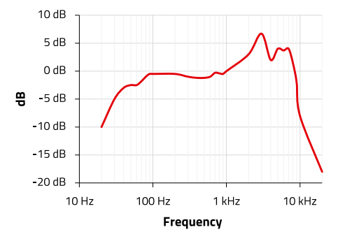
Figure 1: Frequency response of the human ear.
The horizontal axis shows the respective frequency and the vertical axis the reproduction strength of the human auditory system. The auditory system does not pick up sound linearly over the audible frequency range but is more sensitive in some frequency ranges. The sensitivity at frequency of 1 kHz is defined as the 0 dB reference. Generally, if a frequency point is above 1 kHz, it is perceived louder than a 1 kHz sound at the same physical sound pressure. For the sake of simplicity, it is ignored that the auditory system also has a different frequency response for different volumes. The hearing is most sensitive between 2 and 8 kHz, which also happens to be the frequency range of a screaming infant.
Coil whine in this frequency range, is very easily perceived and considered as annoying. A noise at 18 kHz is more likely to go unnoticed, since this frequency is no longer perceived by most people in middle age and hearing is less sensitive at this frequency. However, it is often those coil noises that are in the frequency range of higher sensitivity that are a problem, otherwise they would not have been noticed so quickly in the first place and perceived as annoying.
3. CAUSES OF COIL NOISE
This section clarifies what causes a coil to emit an audible noise. In principle, it is the conversion of electrical quantities into mechanical and finally into acoustic quantities takes place.
3.1 Magnetostriction
Magnetic devices consist of windings and cores. Magnetic cores have the physical property of changing their dimensions when they are exposed to a magnetic field. This widely studied effect is called magnetostriction. Magnetostriction was first observed by J.P. Joule in 1848. When the magnetic field changes periodically, the length of the material also changes periodically - there is an oscillation. In the effect, a compression occurs, followed by an expansion, so that the net volume of the material remains the same.
If the frequency of the changing magnetic field is in the audible range, the core vibration is transmitted to the air so that a sound can be perceived. This effect is commonly heard around 50/60 Hz line frequency transformers as a ‘hum’, particularly around large transformers.
In such a case, a conversion from electrical quantities to mechanical and finally to acoustic quantities takes place, as Figure 2 schematically shows.
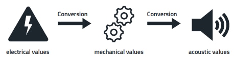
Figure 2: Conversion of electrical quantities into noise
One of the most common cases where acoustic noise occurs is explained using the example of a buck converter, as shown in Figure 3.
3.2 Buck converter
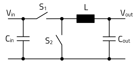
Figure 3: Functional update of a buck converter.
A buck converter is used to convert a defined DC input voltage into a lower DC output voltage. Several electronic components are required for this purpose. Figure 3 shows the functional principle of such a converter. The switch S1, usually realized by a transistor is opened and closed up to several million times per second in typical applications, the control being taken over by an IC. The rectangular pulses are filtered which transfers the input voltage to the output. The coil L and capacitor C supply the load while the switch (S1) is open and the low side switch (S2) is closed. The repeated opening and closing of the switch causes the voltage and current in the circuit to change constantly, creating a changing magnetic field in the coil. These magnetic field changes cause mechanical stresses in the core material of the coil, which leads to a cyclical change in the length of the material due to magnetostriction.
In most cases, the switching frequency of 75 kHz to 2.5 MHz is so high that it is outside the range of human hearing. Nevertheless, audible noise can occur if the duty cycle or the number of pulses of the switching operations varies with a frequency in the audible range.
Burst mode is a special operating state of ICs that allows switching between active and inactive phases to reduce energy consumption. This mode is often used in switching regulators and power supply ICs to increase efficiency at low loads, e.g. stand-by mode.
Due to the high switching frequency of the IC, smaller passive components can be used, which also shortens the settling time. However, if the load falls below a certain threshold value, the IC switches to burst mode, ends continuous switching and instead generates short pulse sequences interrupted by longer rest phases (Figure 4).
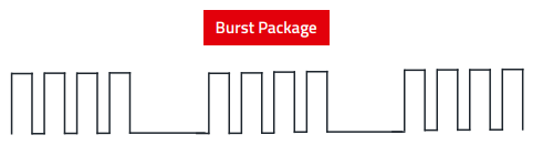
Figure 4: Schematic of Impulse playback in burst mode.
During the active phases in burst mode, the IC supplies the required power for the load to the LC circuit, whereby the mean value of the output voltage after the LC circuit remains constant.A burst packet consists of several switching operations whose frequency is not normally within the audible range. However, there are pauses between the bursts so that the repetition frequency of the burst packets can fall into the audible range.
Not all ICs have this mode, which is why it makes sense to check the switching regulator IC used and determine whether it is operating in burst mode if coil noise occurs.
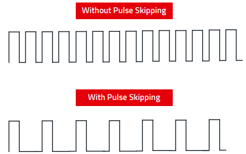
Figure 5: Schematic of pulse skipping pulse playback.
Another operating mode of a buck converter that is similar to burst mode is pulse skipping. As shown in Figure 5, individual or several switching pulses are deliberately skipped in order to keep the output voltage in the desired range. The converter's control loop continuously monitors the output voltage and only intervenes when a correction is required. As a result, the average value of the output voltage remains stable, while the switching frequency is not constant. The effective frequency can fall into the audible range in certain load states if the intervals between the active switching cycles are correspondingly long.
Pulse frequency modulation
Load changes to which the control circuit reacts are also problematic, especially if they occur at a frequency in the audible range and affect the average coil current. This can be caused by external load changes such as a PWM-controlled photo flash control with a frequency below 20 kHz. Another interference factor is inadequate feedback control, as feedback circuits used to stabilize the output voltage often operate in the audible frequency range. As a rule, the idle bandwidth (transition frequency) of the control circuit is well below the switching frequency. This can cause fluctuations in the duty cycle, the frequency of which falls into the audible range and can therefore cause acoustic interference.
3.3 Magnetic flux leakage
In addition to magnetostriction, magnetic flux leakage can play a role in noise generation. In an unshielded inductor, part of the magnetic flux occurs as leakage flux outside the core. The current-carrying windings experience a force due to the magnetic field, which is described by Ampère's force (Laplace's force). In applications where voltage and current change periodically, the windings experience a periodic force effect and accordingly oscillate at a certain frequency. This force is the Lorentz force, which directs individual electrons in a certain direction. The sum of all forces on all electrons results in a movement of the conductor.
The Lorentz force describes the total force on a single moving charged particle due to both the electric and the magnetic field. The Laplace force describes the force on a current-carrying wire in a magnetic field and results from the interaction of the magnetic field with the moving electrons (current) in the wire.
In an air core coil, the windings can move more freely mechanically, whereas in a coil with core material, the resulting forces can also be transferred to the core, causing further mechanical vibrations.
3.4 Natural resonance of components and materials
Depending on the material, dimensions and design of a system, mechanical-acoustic vibrations can be damped or amplified. This effect is specifically used in musical instruments, e.g. a violin, to amplify the vibrations of the strings through the sound box. In simple terms, when the strings are excited, the waves propagate and are then reflected in the resonating body. These overlap with the new waves, so that amplification takes place.
In the context of a circuit, various components and materials are used which have their own resonant frequency due to their mechanical and physical properties. For example, if a coil is vibrated at a frequency of 8 kHz and if the circuit board also oscillates at this frequency, the oscillation amplitude can be amplified by the resonance transmission. This leads to an increase in the sound level, as the resonating body (e.g. the circuit board) amplifies the oscillations of the coil. Without the natural resonance of materials and components, the noise level would be lower and might not even be noticed.
This mechanical-acoustic resonant frequency must not be confused with the resonant frequency specified in the data sheet, which is an electrical property (Figure 6).
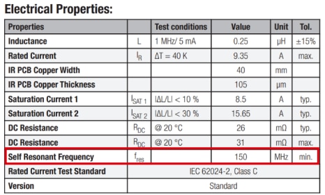
Figure 6: Self Resonant Frequency, fres Self Resonant Frequency.
4. DIAGNOSIS
Before looking for a solution, diagnose where the coil noise is coming from. To find out, a paper can be rolled into a tube and by placing the tube to the ear, various areas of the circuit or environment suspected of causing the noise can be listened to.
A look at the datasheet of the IC provides the necessary information if the IC has a burst mode and in which frequency it works. If the IC does not have a burst mode, this cause can be excluded.
It is also useful to observe if there is a correlation between coil noise and a change in load. As explained in chapter 3, an IC switches to burst mode or pulse skipping when the load is reduced.
In a safety extra low voltage (SELV, < 60 VDC) circuit operating at low temperatures, touching the coil with the tip of a finger should cause the noise to change or fade if the coil is the cause.
Another possibility is to use an oscilloscope with activated FFT (Fast Fourier Transformation) looking at the switch node.
More precise information can be provided by a signal analysis, where at points of suspected noise, the waveform is analyzed to see if it is in the audible frequency range.
It is also useful to observe if there is a correlation between coil noise and a change in load. As explained in chapter 3, an IC switches to burst mode or pulse skipping when the load is reduced. In a safety extra low voltage (SELV, < 60 VDC) circuit operating at low temperatures, touching the coil with the tip of a finger should cause the noise to change or fade if the coil is the cause. Another possibility is to use an oscilloscope with activated FFT (Fast Fourier Transformation) looking at the switch node. More precise information can be provided by a signal analysis, where at points of suspected noise, the waveform is analyzed to see if it is in the audible frequency range.
5. SOLUTIONS
This section presents some possible solutions that can help to reduce or avoid coil noise. However, it should be noted that each solution applies only to a specific case and no universal solution is possible, since the context of the circuit must be considered.
5.1 Coil with low magnetostriction
Since the main cause of coil noise is magnetostriction of magnetic materials, it is advisable to choose a coil with low magnetostriction. The strength of the deformation depends on which material is used for the coil. Coils with ferrite core have higher magnetostrictive deformation compared to iron powder, such as the WE-LHMI, WE-MAPI. Table 1 shows saturation magnetostriction coefficients of various materials. The saturation magnetostriction coefficient quantifies how much the material deforms when the magnetic field reaches its maximum strength. A negative sign indicates that a negative length change occurs and compression takes place when the material is subjected to a magnetic field, and a positive sign indicates a stretching of the physical dimensions.
MnZn ferrites or NiZn ferrites
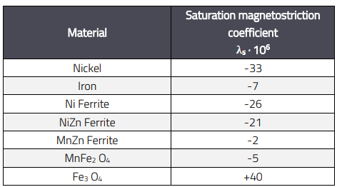
Table 1: Saturation magnetostriction coefficients of different materials.
Since there can be different component options for certain applications, in such a case a component can be considered that meets the specifications of the circuit and has less or no magnetostriction.
5.2 Select a larger size
The closer the peak operating current is to the saturation current, the greater the magnetostrictive length change. If larger components are used, the saturation current is usually higher, as larger components often have a larger core crosssection or more material mass. As a result, the saturation range is reached later and the inductance remains further away from the saturation point.
Since the natural resonant frequency depends on the longest length of the oscillating system, the amplitude and frequency of the resonance can be changed by selecting a larger size.
In addition, a larger component requires a stronger magnetic field to make it oscillate because the inertia of the mass is greater than for a smaller size.
5.3 Change from unshielded to shielded inductor.
By using a shielded inductor, the magnetic field can be contained by closing the magnetic path around the inductor. This applies particularly to core types with a large return path such as drum or bobbin core types.
The additional shielding material also changes the component in terms of its natural resonant frequency and can therefore either dampen or amplify the noise.
5.4 Replace IC
If the causes for the coil noise are in the burst mode or pulse skipping of the IC, then another IC can be used to avoid the burst mode. Here it must be ensured beforehand that the IC meets the specifications of the circuit.
5.5 Adapt load management
If the IC cannot be replaced, then adjusting the load management so that the IC does not go into burst mode or pulse skipping in the first place will also help. As described in section 3.2 a change of the load, especially if it is reduced, triggers the burst mode in the IC. Therefore, the load management must be adjusted so that the burst mode or pulse skipping is not activated in the first place.
5.6 Rotate the coil
Rotating the coil 90° or 180° changes the direction of magnetic flux and its relation to surrounding components and possible interaction with them.
5.7 Additional solutions
To stop the vibrations that cause the noise, the coil in question can be fixed to the circuit board together with the affected component. Another option is to encapsulate the entire electronics, especially if the affected area cannot be precisely localized, several components are affected or all other solutions do not lead to the desired success. However, care must be taken with this method, as adhesives and potting materials can affect the electrical properties of the components, especially the coils. Alternatively, other mechanical fastening options for the circuit board can also contribute to noise reduction.
6. SUMMARY
Noise in electronic components is usually not a cause for concern, since the functioning of the circuit is not affected by a noise, nor is the component involved damaged. In addition to the physical causes, such as magnetostriction, magnetic leakage flux, which is a fundamental property of magnetic materials, psychoacoustic aspects also play a role in perception. Human perception gives the impression that there is a defect that needs to be corrected. Overall, the phenomenon is a complex interplay of many factors that are not immediately apparent from the outset and vary from case to case.
For applications where noise is not desired, Würth Elektronik offers inductors that have a low risk for coil noise, such as the WE-MXGI, WE-MAPI or WE-LHMI. Coils or series such as the WE-TIS and WE-LQ are more susceptible to this in comparison and should be avoided in applications with high requirements for a low-noise environment. The causes of the noise phenomenon cannot be definitively eliminated, but there are possible solutions that can minimize or eliminate noise depending on the influence.
To minimize the risk of coil noise, care should be taken at the circuit design stage to select suitable components that have a low tendency to generate such noise. Inductors and integrated circuits should be carefully selected with regard to their physical and electrical properties, as these can have a significant influence on noise generation.
Especially when selecting ICs, it is important to operate the components according to the manufacturer's specifications and to adjust the switching frequency optimally. A balanced design that considers both performance and noise minimization is crucial.
A APPENDIX
A.1 Literature
[1] J. Smit H.P.J WIJN. Ferrites, Philips' Technical Library.
IMPORTANT NOTICE
The Application Note is based on our knowledge and experience of typical requirements concerning these areas. It serves as general guidance and should not be construed as a commitment for the suitability for customer applications by Würth Elektronik eiSos GmbH & Co. KG. The information in the Application Note is subject to change without notice. This document and parts thereof must not be reproduced or copied without written permission, and contents thereof must not be imparted to a third party nor be used for any unauthorized purpose. Würth Elektronik eiSos GmbH & Co. KG and its subsidiaries and affiliates (WE) are not liable for application assistance of any kind. Customers may use WE’s assistance and product recommendations for their applications and design. The responsibility for the applicability and use of WE Products in a particular customer design is always solely within the authority of the customer. Due to this fact it is up to the customer to evaluate and investigate, where appropriate, and decide whether the device with the specific product characteristics described in the product specification is valid and suitable for the respective customer application or not. The technical specifications are stated in the current data sheet of the products. Therefore, the customers shall use the data sheets and are cautioned to verify that data sheets are current. The current data sheets can be downloaded at www.we-online.com. Customers shall strictly observe any product-specific notes, cautions and warnings. WE reserve the right to make corrections, modifications, enhancements, improvements, and other changes to its products and services. WE DOES NOT WARRANT OR REPRESENT THAT ANY LICENSE, EITHER EXPRESS OR IMPLIED, IS GRANTED UNDER ANY PATENT RIGHT, COPYRIGHT, MASK WORK RIGHT, OR OTHER INTELLECTUAL PROPERTY RIGHT RELATING TO ANY COMBINATION, MACHINE, OR PROCESS IN WHICH WE PRODUCTS OR SERVICES ARE USED. INFORMATION PUBLISHED BY WE REGARDING THIRD-PARTY PRODUCTS OR SERVICES DOES NOT CONSTITUTE A LICENSE FROM WE TO USE SUCH PRODUCTS OR SERVICES OR A WARRANTY OR ENDORSEMENT THEREOF. WE products are not authorized for use in safety-critical applications, or where a failure of the product is reasonably expected to cause severe personal injury or death. Moreover, WE products are neither designed nor intended for use in areas such as military, aerospace, aviation, nuclear control, submarine, transportation (automotive control, train control, ship control), transportation signal, disaster prevention, medical, public information network etc. Customers shall inform WE about the intent of such usage before design-in stage. In certain customer applications requiring a very high level of safety and in which the malfunction or failure of an electronic component could endanger human life or health, customers must ensure that they have all necessary expertise in the safety and regulatory ramifications of their applications. Customers acknowledge and agree that they are solely responsible for all legal, regulatory and safety-related requirements concerning their products and any use of WE products in such safety-critical applications, notwithstanding any applicationsrelated information or support that may be provided by WE. CUSTOMERS SHALL INDEMNIFY WE AGAINST ANY DAMAGES ARISING OUT OF THE USE OF WE PRODUCTS IN SUCH SAFETYCRITICAL APPLICATION.
DIRECT LINK
ANP118 | Acoustic noise & Coil whine effect
USEFUL LINKS:
Application Notes : https://we-online.com/en/support/knowledge/application-notes
Services: https://we-online.com/en/products/components/service
Contact : https://we-online.com/en/support/contact
CONTACT INFORMATION
Würth Elektronik eiSos GmbH & Co. KG
Max-Eyth-Str. 1, 74638 Waldenburg, Germany
Tel.: +49 (0) 7942 / 945 – 0
Email: appnotes@we-online.de