


![]()
Application Notes
Ensuring Safety without Compromising Data Integrity: Critical Characteristics of Digital Isolators
ANS021 by Artem Beliakov
1. INTRODUCTION
In today's rapidly evolving technology landscape, the demand for digital isolators has grown rapidly, driven by the increasing need for safety, isolation and high data rates in modern electronic systems. Digital isolators, which are critical components in many applications, perform the essential function of electrically isolating circuits while ensuring the smooth transfer of data between different parts of the system. This dual role is becoming increasingly important as industries push for greater automation, efficiency and safety standards. Whether in industrial automation, automotive systems or consumer electronics, the reliability and performance of digital isolators are of paramount importance. Using Würth Elektronik products as an example, this article examines the critical parameters of digital isolators and provides a complete overview of the key characteristics that design engineers should consider when selecting the right digital isolator for their applications.
2. SAFETY STANDARDS
The primary function of digital isolators is to ensure the safety of equipment and people. Whenever high voltages can damage sensitive circuitry or injure a person, isolation is required. That is why safety certification is so important. International safety standards regulate the testing of isolation voltage and many other isolation characteristics. All standards provide methods, parameters and requirements for testing. To obtain such certifications, digital isolators must pass rigorous testing procedures. Table 1 lists the international safety standards to which Würth Elektronik digital isolators are certified.
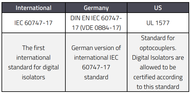
Table 1: International standards.
UL 1577 was developed as a safety standard for optocouplers but is also used to certify magnetic and capacitive isolators. According to this standard, a certified device's isolation barrier must withstand a certain level of RMS AC voltage (VISO) for 60 seconds. At a minimum, a digital isolator must withstand an isolation test voltage of 1.2 · VISO for 1 second.
The maximum isolation withstands voltage (VISO(max)) for Würth Elektronik's powered and unpowered digital isolators is shown in Table 2.
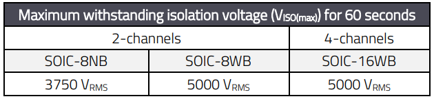
Table 2: Isolation voltage according to UL 1577.
IEC 60747-17 is the first standard specifically designed for the certification of capacitive and magnetic digital isolators. It is the most modern applicable standard that allows digital isolators to be used in safety-critical applications. DIN EN IEC 60747-17 (VDE 0884-17) is the German version of the international IEC standard.
The standard includes four types of isolation voltages: maximum working voltage, maximum repetitive peak voltage, maximum transient voltage and maximum surge isolation voltages (interpreted meaning based on the application).
2.1 Maximum Working Isolation Voltage (VIOWM)
This parameter defines the maximum continuous working voltage that can be applied to the isolation barrier continuously over the lifetime of a digital isolator without degrading its functionality. This characteristic is defined as RMS- or DC-voltage.
2.2 Maximum Repetitive Peak Isolation Voltage (VIORM)
This is the maximum repetitive peak voltage that can be continuously applied to the isolation barrier over the lifetime of a digital isolator without reducing its functionality. Maximum repetitive peak isolation voltage is defined as a peak value.
2.3 Maximum Transient Isolation Voltage (VIOTM)
This is the maximum peak voltage that can be applied to the isolation barrier for 60 seconds. The characteristic is defined as a peak voltage value.
2.4 Maximum Surge Isolation Voltage (VIOSM)
A maximum instantaneous value of a voltage pulse (1.2/50 µs waveform) that an isolator can tolerate. The property is defined as a peak voltage value. Isolation voltage types for all Würth Elektroniks’ digital isolators are specified in Table 3. There are many different levels of isolation defined. The main ones are functional, basic and reinforced (interpreted meaning based on the application).
- Functional isolation provides only necessary isolation for the correct operation of the system and doesn’t protect against electric shock.
- Basic isolation provides protection against electric shock in addition to functional isolation.
- Compared to an isolator that provides basic isolation, an isolator that provides reinforced isolation (equivalent to double isolation) has higher test voltage requirements.
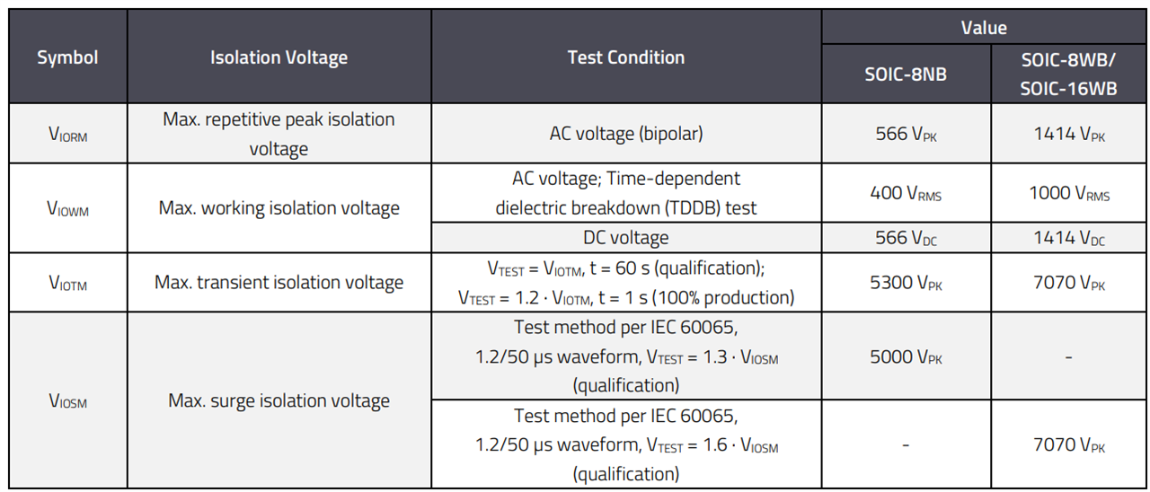
Table 3: Isolation voltages according DIN EN IEC 60747-17 (VDE 0884-17):2021-10.
According to IEC 60747-17 and VDE 0884-17 standards an isolator must pass the surge test at a peak voltage of 1.3 times VISOM for basic isolation and 1.6 times VISOM for reinforced isolation. The minimum surge voltage for reinforced isolation should be greater than 10 kV. Failure rate over lifetime is less than 1000 ppm for basic isolation and less than 1 ppm for reinforced isolation.
Würth Elektronik digital isolators in SOIC-8NB package provide basic level of isolation and reinforced isolation for the digital isolators in SOIC-8WB and SOIC-16WB packages. The difference between basic and reinforced isolation is shown in Table 4 using Würth Elektronik products as an example.
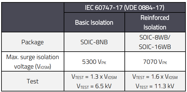
Table 4: Basic isolation vs. reinforced isolation.
3. CREEPAGE AND CLEARANCE DISTANCE
Creepage and clearance distance are closely related to the level of isolation and play an important role in preventing arcing and ensuring the safety of the isolator.
- Clearance is the shortest distance through air between input and output terminals of an isolator.
- Creepage is the shortest distance across the surface of the package between two conductive parts of an isolator. Figure 1 shows the definition of the creepage and clearance distances at a digital isolator.
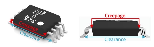
Figure 1: Creepage and Clearance distance.
Creepage and clearance distance is 8 mm for digital isolators in SOIC-16WB and SOIC-8WB packages and 4 mm for isolators in SOIC-8NB package.
4. COMPARATIVE TRACKING INDEX (CTI)
In addition to creepage and clearance distance, a package's technology and the quality of the molding compound affect the isolation rating. Comparative Tracking Index (CTI) indicates the ability of the package mold compound to withstand constant high voltage stress without surface degradation. A higher Comparative Tracking Index (CTI) means that the insulating material has a higher tracking resistance. This means that it can withstand a higher voltage without creating a conductive path on its surface that allows a leakage current. With a higher CTI, the housing can therefore be smaller for the same assumed high-voltage load Table 5 shows the material classification by CTI.
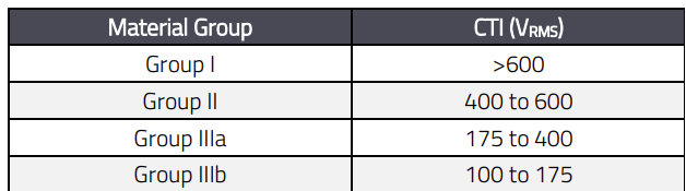
Table 5: Comparative Tracking Index.
The WE digital isolators provide CTI of more than 600 VRMS and correspond to the material group I.
5. TIMING CHARACTERISTICS
5.1 Data Rate (DR)
We live in a world where electronic devices communicate with each other using digital signals and the data transmission speed of these signals is increasing from year to year. Therefore, it is important not only to provide the necessary level of galvanic isolation, but also to ensure reliable transmission of high-speed data. As a result, the timing characteristics of digital isolators, such as data rate or propagation delay, are just as important as their isolation properties. Digital isolators meet these needs by offering superior isolation properties without compromising data integrity or speed.
Data rate is the number of bits transmitted per second or the highest speed at which data can pass through the device. The most common interfaces on the market that allow communication between electronic devices in different applications are shown in Figure 2. The approximate data rates for each are also shown.
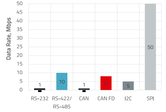
Figure 2: Interfaces vs. Data Rate.
Applications for interfaces:
- RS-232 is used in modems, printers and PLC machines. The maximum data rate is up to 1 Mbps, but usually it is less than 500 kbps.
- RS-422 and RS-485 are used in industrial automation, smart meters, HVAC (Heating, Ventilation and Air Conditioning) systems, motor drives and tools. The data rate is up to 10 Mbps.
- CAN and CAN FD (Controller Area Network Flexible DataRate) are used in industrial automation, automotive, transportation electronics, industrial control systems, building automation and HVAC systems. The CAN data rate is up to 1 Mbps, whereas the data rate for CAN FD is in the range of 5 to 8 Mbps.
- I 2C - is suitable for applications where simplicity and low manufacturing cost are more important than speed. The main applications are low speed DAC/ADC, LCD or OLED displays, various types of sensors (e.g., temperature, light, humidity, pressure, etc.). The data rate is up to 5 Mbps.
- SPI is the fast interface for communication between controllers, sensors and memory modules and the data rate is up to 50 Mbps.
The optocoupler’s frequency responses limits it for high speed applications. Digital isolators are the best solution for this task. Würth Elektronik digital isolators offer data rates up to 150 Mbps and cover the most common applications on the market.
5.2 Propagation Delay
Digital isolators transmit signals across an isolation barrier. This is accomplished by using a modulator to transmit high frequency signals through the barrier. The receiver demodulates the high frequency signal into an output signal. The internal structure of Würth Elektroniks’ capacitive digital isolators is shown in Figure 3.
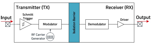
Figure 3: Internal structure of capacitive digital isolators from Würth Elektronik.
Propagation delay is the time it takes for a digital signal to pass through the internal circuits and structure of a digital isolator from input to output (Figure 4). This is the critical parameter for high-speed interfaces (e.g., for SPI bus) and for applications where a digital isolator is a part of a time-critical application.
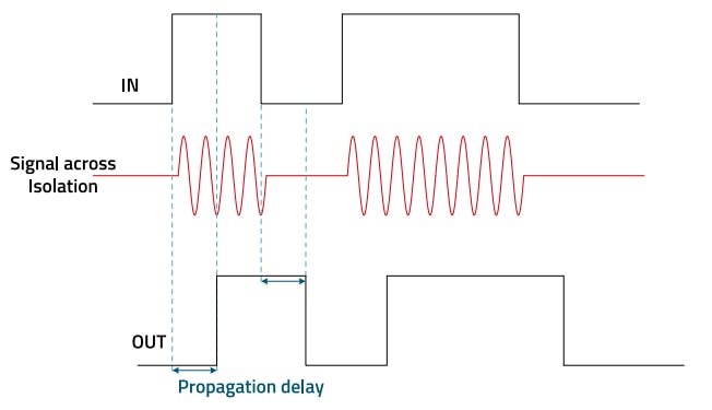
Figure 4: Propagation Delay between IN and OUT in a digital isolator.
Propagation delay skew is a time delay deviation between different channels of the same digital isolator (channel-tochannel output skew time) or between digital isolators of the same type (part-to-part output skew time). This parameter is particularly critical for data buses.
The timing characteristics of Würth Elektronik digital isolators are given in Table 6.
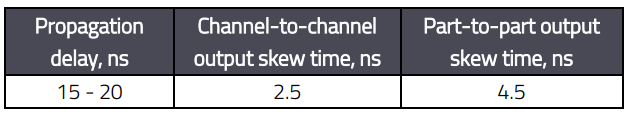
Table 6: Timing characteristics.
6. DEFAULT OUTPUT STATE
Default output state is a predefined state of the output signal pin when the input side of the isolator is not powered, or the input signal pin is open (not connected). Digital isolators can provide default output state ‘’high’’ or default output state ‘’low’’. Selecting the right digital isolator depends on the specific application. Before describing the various applications, it is necessary to understand the difference in the operation of digital isolators with different default output states.
The modulator (Figure 3) of the digital isolator with low default output state transmits high-frequency signals through the isolation barrier only when the input has a high signal level (Figure 5).
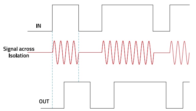
Figure 5: Modulator operation mode for digital isolators with default low output.
And vice versa, the modulator of the digital isolator with high default output state transmits high-frequency signals through the isolation barrier only when the input has a low signal level (Figure 6).
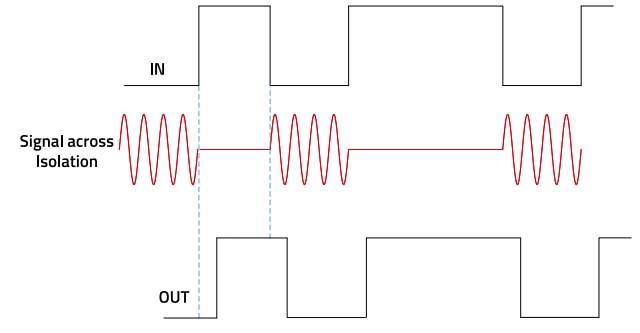
Figure 6: Modulator operation mode for digital isolators with default high output.
Many communication interfaces, like I2C and UART have a high logic level in standby mode (idle mode). This means that digital isolators with a default high output state will consume less power in this mode than digital isolators with a default low output state, because the internal modulator of high frequency signals is not operating during this time (standby mode). This is an important consideration, especially for systems with battery power supply.
As another example, digital isolators with default low output state are preferred for use in switch mode power supplies (SMPS) to isolate gate drivers for safety reasons, or for interface topologies like SPI and CAN in case there are low in standby.
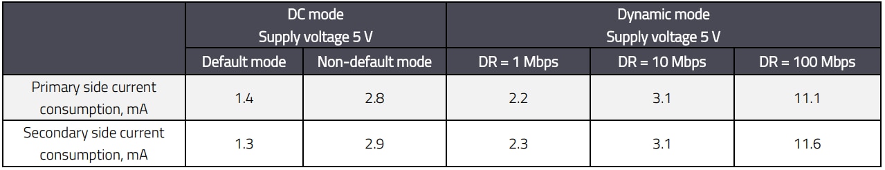
Table 7: Typical current consumption for 18012115411H
7. CURRENT CONSUMPTION
As can be seen, the current consumption of the digital isolator is related to the default output state. Usually, in a datasheet, the current consumption of digital isolator is specified in default output mode (internal modulator of high-frequency signals does not operate) and in non-default output mode (internal modulator of high-frequency signals operates constantly). We can call these modes static consumption or DC mode.
Obviously, the current consumption in default output mode will be lower than in non-default output mode. The technical specifications also provide dynamic current consumption values that depend on the data transfer rate. The higher the data transfer rate, the higher the current consumption. The dynamic current consumption for Würth Elektronik digital isolators is given for data rates of 1 Mbps, 10 Mbps and 100 Mbps. The current consumption example for 2-channel digital isolator 18012115411H is shown in Table 7.
8. COMMON MODE TRANSIENT IMMUNITY (CMTI)
CMTI is an important parameter because high slew rate transients, which then also have high frequency components, can affect data transmission across the isolation barrier. The parasitic capacitance between the barrier (i.e., between the isolated ground planes) provides the path for these fast transients to cross the isolation barrier and distort the output signal. During the CMTI test, a pulsed transient is applied across the isolated ground planes GND1 and GND2. A digital signal is fed to the inputs and the outputs of the isolator are monitored for data distortion. This is particularly important for high-speed data transmission.
Würth Elektronik’s digital isolators offer high immunity to system noise with a typical CMTI level of ±150 kV/µs, allowing them to be used in harsh environments with strong magnetic fields, overvoltage, transients and high electromagnetic interference. Figure 7 illustrates a CMTI testing scheme.
9. ELECTROSTATIC DISCHARGE (ESD)
Electrostatic discharge (ESD) is a sudden flow of electricity between two charged objects that occurs when they come into contact or close proximity, resulting in a discharge of static electricity. ESD protection is critical in the electronics industry because ESD can cause immediate and latent damage to components, resulting in performance degradation, reduced reliability, lower manufacturing yields, and increased repair or replacement costs.
Industry standards define testing models to simulate typical ESD events and protect electronic components from damage. They are used in electronics manufacturing to test the resistance of components to electrostatic discharge. The two most common models are:
- Human Body Model (HBM): This model simulates the discharge from a human body to a device. It is characterized by a high-resistance discharge event.
- Charged Device Model (CDM): The CDM simulates the scenario where a charged device discharges into a grounded surface. This model typically involves higher current peaks.
Würth Elektronik digital isolators offer HBM withstand voltage of up to 6 kV and CDM withstand voltage of up to 2 kV.
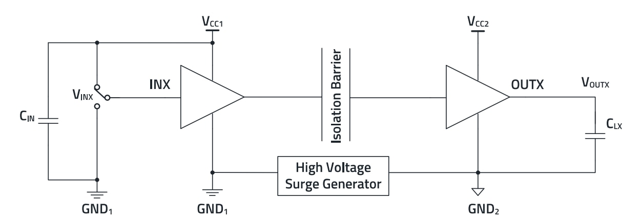
Figure 7: CMTI test schematic.
10. CONCLUSION
Digital isolators have become indispensable in modern electronic systems to meet the dual requirements of safety and high-speed data transmission. As technological advances continue to accelerate, the importance of selecting the right digital isolator with the appropriate specifications cannot be overstated. This includes understanding safety standards, isolation voltages, timing characteristics and other critical parameters to ensure optimal performance and reliability. Würth Elektronik's digital isolators exemplify this by meeting all of today's safety standards and requirements, making them a reliable choice for various applications. By fully understanding their key parameters, engineers can make informed decisions that improve system performance and safety.
IMPORTANT NOTICE
The Application Note is based on our knowledge and experience of typical requirements concerning these areas. It serves as general guidance and should not be construed as a commitment for the suitability for customer applications by Würth Elektronik eiSos GmbH & Co. KG. The information in the Application Note is subject to change without notice. This document and parts thereof must not be reproduced or copied without written permission, and contents thereof must not be imparted to a third party nor be used for any unauthorized purpose. Würth Elektronik eiSos GmbH & Co. KG and its subsidiaries and affiliates (WE) are not liable for application assistance of any kind. Customers may use WE’s assistance and product recommendations for their applications and design. The responsibility for the applicability and use of WE Products in a particular customer design is always solely within the authority of the customer. Due to this fact it is up to the customer to evaluate and investigate, where appropriate, and decide whether the device with the specific product characteristics described in the product specification is valid and suitable for the respective customer application or not. The technical specifications are stated in the current data sheet of the products. Therefore the customers shall use the data sheets and are cautioned to verify that data sheets are current. The current data sheets can be downloaded at www.we-online.com. Customers shall strictly observe any product-specific notes, cautions and warnings. WE reserves the right to make corrections, modifications, enhancements, improvements, and other changes to its products and services. WE DOES NOT WARRANT OR REPRESENT THAT ANY LICENSE, EITHER EXPRESS OR IMPLIED, IS GRANTED UNDER ANY PATENT RIGHT, COPYRIGHT, MASK WORK RIGHT, OR OTHER INTELLECTUAL PROPERTY RIGHT RELATING TO ANY COMBINATION, MACHINE, OR PROCESS IN WHICH WE PRODUCTS OR SERVICES ARE USED. INFORMATION PUBLISHED BY WE REGARDING THIRD-PARTY PRODUCTS OR SERVICES DOES NOT CONSTITUTE A LICENSE FROM WE TO USE SUCH PRODUCTS OR SERVICES OR A WARRANTY OR ENDORSEMENT THEREOF. WE products are not authorized for use in safety-critical applications, or where a failure of the product is reasonably expected to cause severe personal injury or death. Moreover, WE products are neither designed nor intended for use in areas such as military, aerospace, aviation, nuclear control, submarine, transportation (automotive control, train control, ship control), transportation signal, disaster prevention, medical, public information network etc. Customers shall inform WE about the intent of such usage before design-in stage. In certain customer applications requiring a very high level of safety and in which the malfunction or failure of an electronic component could endanger human life or health, customers must ensure that they have all necessary expertise in the safety and regulatory ramifications of their applications. Customers acknowledge and agree that they are solely responsible for all legal, regulatory and safety-related requirements concerning their products and any use of WE products in such safety-critical applications, notwithstanding any applicationsrelated information or support that may be provided by WE. CUSTOMERS SHALL INDEMNIFY WE AGAINST ANY DAMAGES ARISING OUT OF THE USE OF WE PRODUCTS IN SUCH SAFETYCRITICAL APPLICATION.
DIRECT LINK
USEFUL LINKS:
Application Notes : https://we-online.com/en/support/knowledge/application-notes
Services: https://we-online.com/en/products/components/service
Contact : https://we-online.com/en/support/contact
CONTACT INFORMATION
Würth Elektronik eiSos GmbH & Co. KG
Max-Eyth-Str. 1, 74638 Waldenburg, Germany
Tel.: +49 (0) 7942 / 945 – 0
Email: appnotes@we-online.de
