Current sensors
Fundamentals
Measuring principles current sensors
Current Transformers (CTs) operate on the principle of inductive coupling, where the primary current induces a magnetic field in the core, which in turn induces a current in the secondary winding proportional to the primary current. Due to their design and construction, CTs are typically bulky in size. They are primarily designed for measuring alternating current (AC) and are not suitable for direct current (DC) measurements. Despite their limitations, CTs find widespread applications in electrical power systems for various purposes such as current monitoring, protection, and metering. They are commonly used in power distribution networks, electrical substations, industrial facilities, and renewable energy systems.
Rogowski is also used to measure AC current with principle of inductive coil without a magnetic Core. It measure the rate of change of current. Rogowski coils are flexible and can be easily wrapped around irregularly shaped conductors, making them suitable for a wide range of applications where CTs may not fit or require complex installation. They can also measure only AC.
Shunt resistors are typically resistors placed in series with the circuit through which the current is to be measured. When current flows through the circuit, a voltage drop occurs across the shunt resistor proportional to the current passing through it. In high-current applications, it can lead to significant power dissipation and heat generation, requiring additional cooling measures or derating of the resistor's power rating. They are typically used in Battery Management Systems, Power supplies and converters, motor control and devices.
FOCS (Fiber-optic current sensor) are based on the Faraday effect, where the polarization of light changes when it passes through a medium subjected to a magnetic field, which is proportional to the current flowing through a conductor. more expensive due to the use of fiber optics and associated electronics used in electric power systems, high-voltage environments, and areas requiring isolation. Also, high frequency response capabilities, making them suitable for various high-frequency current measurement applications.
xMR (Magnetic Resistance) current sensors operate based on the principle of magnetoresistance, specifically utilizing the anisotropic magnetoresistance (AMR) effect or the giant magnetoresistance (GMR) effect. These effects describe the change in the electrical resistance of a material in response to an applied magnetic field. In xMR current sensors, a magnetic material with variable resistance is placed in the magnetic field generated by the current-carrying conductor. As the magnetic field changes due to the current flowing through the conductor, the resistance of the material also changes proportionally. This change in resistance is measured and calibrated to determine the magnitude of the current.
In renewable energy systems such as solar inverters and wind turbines, xMR current sensors are used for current monitoring in power conversion and energy storage systems. They assist in optimizing energy harvesting, ensuring efficient operation, and maintaining system reliability.
xMR current sensors are used in automotive systems for current monitoring in battery management systems, motor control units, and safety systems.
Hall effect sensor measure the magnetic field generated by the current flow in a conductor. As the current flows through the conductor, it creates a magnetic field perpendicular to both the current and the Hall element. The Lorentz force causes the charge carriers in the semiconductor material to be deflected, resulting in the accumulation of charge on one side of the Hall element and an equal and opposite charge accumulation on the other side, generating a voltage difference proportional to the applied magnetic field and, consequently, the current being measured. This Hall voltage is then measured and calibrated to determine the magnitude of the current flowing through the conductor.
Hall-based current sensors find widespread applications in various industries, including automotive, industrial automation, power distribution, and consumer electronics. They are used for current monitoring, overcurrent protection, motor control, and energy management applications, offering advantages such as galvanic isolation, high accuracy, and wide dynamic range, making them indispensable in modern electrical systems.
WE-RCDS
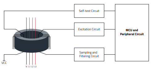
Flux gate sensors measures the changes in magnetic flux density induced by the current-carrying conductor. It consists of a core made of magnetically permeable material and excitation coils. The core's magnetic properties change with the applied current, allowing for current measurement. Fluxgate sensors are highly sensitive to changes in magnetic fields, making them suitable for detecting weak magnetic fields with high accuracy.
In industrial automation, fluxgate current sensors are used for current monitoring in motor control systems, process control equipment, and machinery. They provide accurate feedback for controlling motor speed, torque, and power consumption in manufacturing, robotics, and material handling applications.
Fluxgate current sensors are employed in power electronics for monitoring and controlling currents in converters, inverters, motor drives, and power distribution systems.
MEASURING PRINCIPLES
FLUX GATE SENSORS
WE-RCDS

Open loop
The excitation coil drives the core into saturation and de-saturates it again. This also happens in the negative direction, so that the typical hysteresis of the soft magnetic core is operated. Without an external magnetic field, the induced voltage at the sampling resistor is symmetrical. The symmetry is interrupted by a fault current and the resulting external magnetic field. This can now be demodulated via a filter so that the fault current is detected. Current can be demodulated by hardware filter or digital filter.

Closed loop
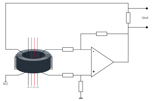
A compensation winding is used which counteracts the magnetic field of the fault current in the reverse direction. The aim is to ensure that the magnetic field of the fault current is fully compensated. The fault current can be calculated by using the current required for compensation.
If you want to read more find here the whole Product Guide.

