

REFERENCE DESIGN NOTE -  LED Driver with MagI3C Power Module
DNS001: BY ROLAND KRATZ
MagI3C Power Modules
VDRM - LED Driver Application
7 - 24V INPUT / 0 – 1.5A LED CURRENT
1. Introduction
The DNS14 is a reference design for the WLMDU9456008T LED driver capable of driving up to 1.5 A output current using a voltage regulated module and an external secondary regulation loop to establish current regulation. The external loop regulates a DC output current which results in a constant photon flow. Compared to other solutions with PWM, this solution is less harmful to the eyes due to the constant photon flow, allowing the pupil opening to be the proper size for the light intensity emitted. Depending on the LED flux voltage up to 4 LEDs in series can be connected.
2. Features
Input voltage range from 7 V to 24 V
- Output current up to 1.5 A
- Adjustable current from 10 mA to 1.5 A
- Dimming voltage 0 V (10 mA) to 5 V (1.5 A)
- Current regulation
- Output current ripple typ. < 10 mA
- Output power up to 22.5 W
- Series connected LEDs up to 15 V total flux voltage
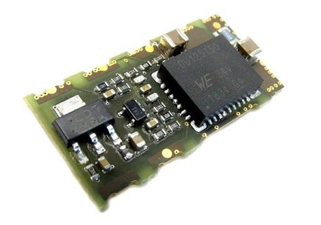
Figure 1: Development Example
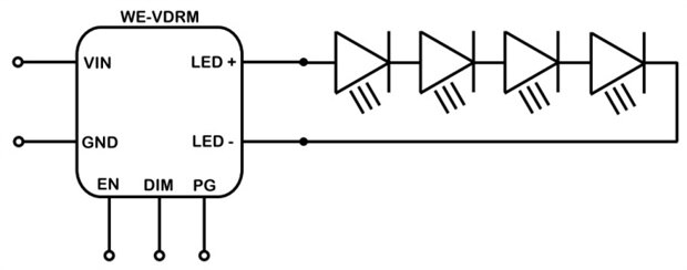
Figure 2: Simplified Schematic
3. Description
The power consumption of LEDs on the lighting market is constantly increasing. LEDs require currents of 700 mA, 1 A or higher. High output currents are supported commonly with voltage regulated modules. Constant high current led drivers are uncommon on the market. This design note describes how to convert a voltage regulated module to a current regulated module. Typical supplies for LEDs are modules operating as current sources. They include dual protection against output short circuits. A current regulated circuit is - if designed properly - short circuit protected by itself due to its nature of forcing a defined current into the load regardless if the load is an LED or a low resistance like a short circuit. The second overcurrent protection circuit is integrated in the module commonly through a cycle by cycle current limit.
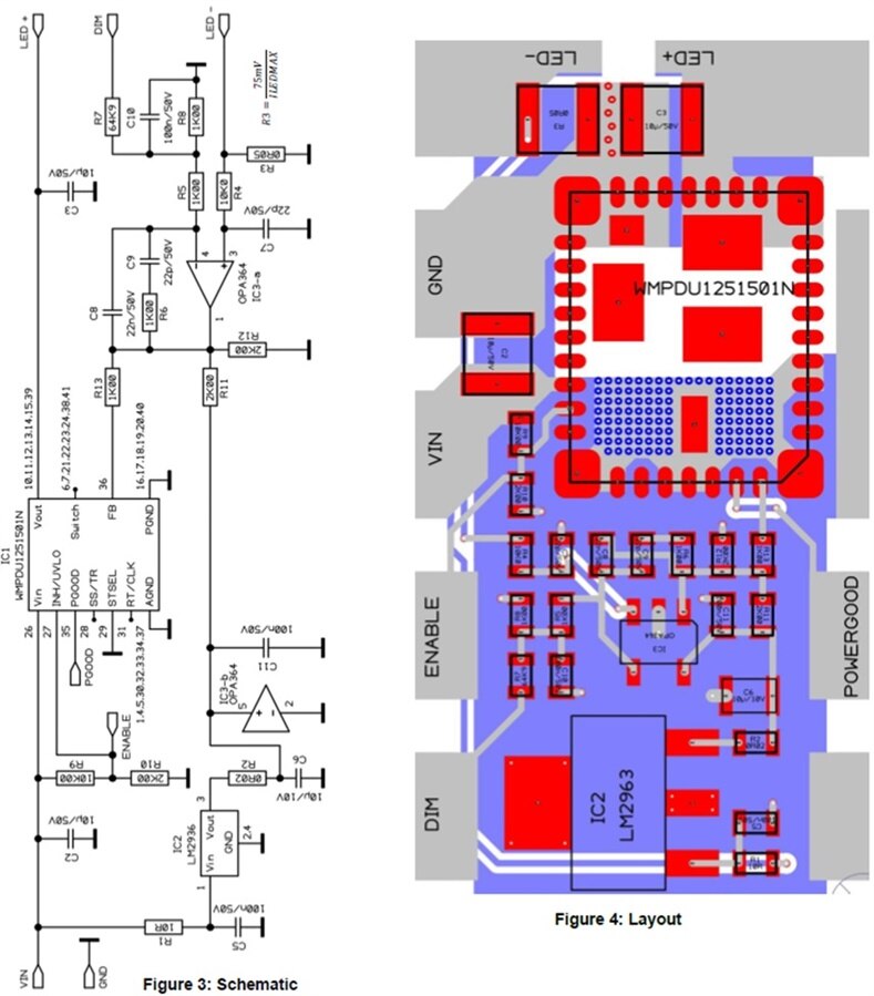
A MagI3C VDRM module is used in this application. Natively it is voltage regulated. The current through a specific number of LEDs will flow from LED+ pin through the LEDs to the LED- pin. The LED current flows through a shunt resistor, R3, and the voltage across R3 is compared with a dimming voltage. A 5 V dimming voltage at the DIM terminal results in a voltage of 75 mV at the regulation loop amplifier (IC3, pin4) with which the shunt voltage (IC3, pin 3) is compared. IC3 is used for an outer and slower regulation circuit which drives the feedback pin of the VDRM module. The compensation network consists of C8, C9 and R6, which may be trimmed by the design engineer depending on the customer PCB layout if modified from the reference design PCB layout.
An external dimming (adjusting) voltage is always required. This can be derived directly from VIN if stable or from a resistor divider from the 3.3 V of the linear regulator (IC2). The supply of the operational amplifier is derived from VIN with a linear regulator (IC2) with a capability of abs. max. 40V or 60V input voltage. Its output voltage is set to 3.3V. The Input voltage of the design ranges from 7 V to 50 V (only with the 60 V version of the LM2936, which is not available in this small package) and the output current ranges from 0 A to 2.5 A. Note that the output power shall not exceed 22.5 W. The compensation may be adapted for various operating points.
This Reference Design is developed using the following specification:
Vin = 7 V - 24 V Vout = 0 V - 15 V Iout = 10 mA - 1.5 A
4. Bill of Material
Index | Description | Size | Value | Order Code | Supplier |
IC1 | MagI3C power module | BQFN-41 | WPMDU1251501N | 171 021 501 | Würth Elektronik eiSos |
IC2 | Linear regulator | SOT-223 | LM2936(HV) | LM2936MP-3.3 (40V) | Texas Instruments |
IC3 | Operational amplifier | SOT-23 | OPA364 | Texas Instruments | |
R5,R6,R8,R13 |
| 0603 1% TK100 125mW | 1K00 |
|
|
R10,R11,R12 |
| 0603 1% TK100 125mW | 2K00 |
|
|
R1 |
| 0603 5% TK100 125mW | 10R0 |
|
|
R2 |
| 0603 5% TK100 125mW | 0R02 |
|
|
R4,R9 | Change R9 to your UVLO needs | 0603 1% TK100 125mW | 10K0 |
|
|
R7 | Defines max current at 5 V at DIM pin/pad (5 V = 1.5 A) | 0603 1% TK100 125mW | 64K9 |
|
|
R3 | Shunt resistor | 1210 0,5% 250mW | 0R05 |
|
|
C2,C3 |
| X5R or X7R 1210 10% | 10μ/50V |
|
|
C5,C10,C11 |
| X7R 0603 10% | 100n/50V | 885 012 206 095 | Würth Elektronik eiSos |
C7,C9 |
| COG,NP0 0603 10% | 22p/50V | 885 012 006 053 | Würth Elektronik eiSos |
C8 |
| X7R 0603 10% | 22n/50V | 885 012 206 091 | Würth Elektronik eiSos |
C6 |
| X5R 0805 20% | 10μ/10V | 885 012 107 010 | Würth Elektronik eiSos |
Table 1: Bill of Material
5. Schematic and Layout
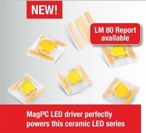
6. Suitable Würth Elektronik eiSos High power LEDs
WL-SWTC
SMD White Top View Ceramic LED
Size 3535, waterclear dome lens
| Characteristics | Applications |
|
|
Electrical & Optical Characteristics @ 0.35 A (typ.) | ||||||||
Order Code | Emitting Color | CCT | CRI | ΦV | VF | Chip Technology | 2θ50% | |
Sunrise | 2700 | 80 | 95 | 3.2 | InGaN | 120 | ||
Warm White | 3000 | 80 | 95 | |||||
Moonlight | 4000 | 75 | 110 | |||||
Daylight | 5000 | 70 | 121 | |||||
Cool White | 6000 | 70 | 121 | |||||
CCT = Correlated Color Temperature CRI = Color Rendering Index ΦV = Luminous Flux VF = Forward Voltage 2θ50% = Viewing Angle | ||||||||
Figure 5: Recommended High Power White LEDs
WL-SMDC
Ceramic mono-color High Power LED
Size 3535, waterclear
 | Characteristics | Applications |
|
|
Electrical & Optical Characteristics @ 0.35 A (typ.) | ||||||||
Order Code | Emitting Color | λPeak typ. | λDom typ. | ΦV | VF typ. | Chip Technology | 2θ50% | |
Red | 635 | 625 | 55 |
| AlInGaP | 125 | ||
Yellow | 593 | 590 | 50 |
| AlInGaP | |||
Green | 520 | 525 | 85 |
| InGaN | |||
Blue | 455 | 460 | 25 |
| InGaN | |||
λPeak = Peak Wavelength λDom = Dominant Wavelength ΦV = Luminous Intensity VF = Forward Voltage 2θ50% = Viewing Angle | ||||||||
Figure 6: Recommended High Power Colored LEDs
IMPORTANT NOTICE
The Application Note is based on our knowledge and experience of typical requirements regarding these areas: It serves as general guidance and should not be construed as a commitment for the suitability for customer applications by Würth Elektronik eiSos GmbH & Co. KG. The information in the Application Note is subject to change without notice. This document and parts thereof must not be reproduced or copied without written permission, and contents thereof must not be imparted to a third party nor be used for any unauthorized purpose. Würth Elektronik eiSos GmbH & Co. KG and its subsidiaries and affiliates (WE) are not liable for application assistance of any kind. Customers may use WE’s assistance and product recommendations for their applications and design. The responsibility for the applicability and use of WE Products in a particular customer design is always solely within the authority of the customer. Due to this fact it is up to the customer to evaluate and investigate, where appropriate, and decide whether the device with the specific product characteristics described in the product specification is valid and suitable for the respective customer application or not. The technical specifications are stated in the current data sheet of the products. Therefore the customers shall use the
data sheets and are cautioned to verify that data sheets are current. The current data sheets can be downloaded at www.we-online.com. Customers shall strictly observe any product-specific notes, cautions and warnings. WE reserves the right to make corrections, modifications, enhancements, improvements, and other changes to its products and services. WE DOES NOT WARRANT OR REPRESENT THAT ANY LICENSE, EITHER EXPRESS OR IMPLIED, IS GRANTED UNDER ANY PATENT RIGHT, COPYRIGHT, MASK WORK RIGHT, OR OTHER INTELLECTUAL PROPERTY RIGHT RELATING TO ANY COMBINATION, MACHINE, OR PROCESS IN WHICH WE PRODUCTS OR SERVICES ARE USED. INFORMATION PUBLISHED BY WE REGARDING THIRD-PARTY PRODUCTS OR SERVICES DOES NOT CONSTITUTE A LICENSE FROM WE TO USE SUCH PRODUCTS OR SERVICES OR A WARRANTY OR ENDORSEMENT THEREOF.
WE products are not authorized for use in safety-critical applications, or where a failure of the product is reasonably expected to cause severe personal injury or death. Moreover, WE products are neither designed nor intended for use in areas such as military, aerospace, aviation, nuclear control, submarine, transportation (automotive control, train control, ship control), transportation signal, disaster prevention, medical, public information network etc. Customers shall inform WE about the intent of such usage before design-in stage. In certain customer applications requiring a very high level of safety and in which the malfunction or failure of an electronic component could endanger human life or health, customers must ensure that they have all necessary expertise in the safety and regulatory ramifications of their applications. Customers acknowledge and agree that they are solely responsible for all legal, regulatory and safety-related requirements concerning their products and any use of WE products in such safety-critical applications, notwithstanding any applicationsrelated information or support that may be provided by WE. CUSTOMERS SHALL INDEMNIFY WE AGAINST ANY DAMAGES ARISING OUT OF THE USE OF WE PRODUCTS IN SUCH SAFETY-CRITICAL APPLICATIONS.
USEFUL LINKS
Application Notes:
http://www.we-online.com/app-notes
Component Selector:
http://www.we-online.com/component-selector
Toolbox:
http://www.we-online.com/toolbox
Product Catalog:
http://katalog.we-online.de/en/
CONTACT INFORMATION
Würth Elektronik eiSos GmbH & Co. KG
Max-Eyth-Str. 1, 74638 Waldenburg, Germany
Tel.: +49 (0) 7942 / 945 – 0
Email: appnotes@we-online.de