


EMC Basics: Common Mode vs. Differential Noise
Author: Dheeraj Jain, Technology Strategist; Jenna Cummins
Today, we will talk about the differences between common mode and differential noise in EMC and how to combat them.
Common Mode vs. Differential Noise
As a quick reminder, differential currents flow in opposite directions through the source and return path, while common mode currents flow the same direction through the source and return path, completing the circuit through the ground path.
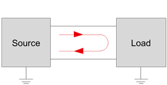
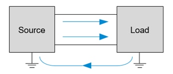
Differential mode noise path Common mode noise path
Figure 1. Differential mode and common mode noise paths
How to know if you are dealing with common mode noise or differential noise? This is a common question that needs to be answered.
Here's a quick trick to getting you headed in the right direction. While it's not 100% accurate, it helps get the process started.
Imagine a doctor prescribing antibiotics without knowing whether you have a bacterial infection or a virus. He does so knowing that if you have a bacterial infection, the medication will work, and the problem will be solved. If the medication does not work, at least he knows he’s dealing with a virus, and will then treat you accordingly.
So in our case, you can simply apply a clamp-on ferrite onto a cable, remembering both lines (Vcc and ground) will be in that cable. If the noise is reduced (or the immunity is increased) then you’re experiencing a common mode problem. If there's no effect, it’s a differential mode problem.
Therefore, at the board level, if it is a common mode problem, you can use a common mode choke. If the problem is differential mode, a chip bead ferrite can be used.
Material Characteristics
Clamp-on ferrites are typically made with two different types of materials: manganese zinc (MnZn) and nickel zinc (NiZn).
Nickel zinc can be used in situations with either conducted or radiated noise at high frequencies. Manganese zinc is mostly used for conductive noise at lower frequencies because its higher permeability gives more impedance.
This image provides a guideline for which material to use depending on your situation. Of course, there are exceptions, but this is what we find to be typical.
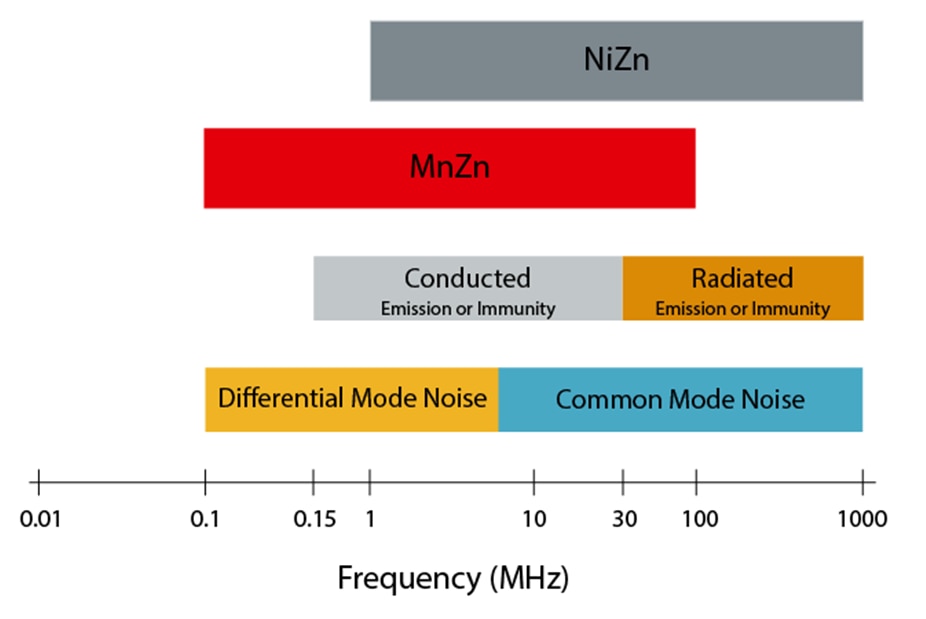
Figure 2. Materials for clamp-on ferrites, where conducted and radiated immunity are tested and the common frequency range where differential and common mode noise occur.
Reducing Common Mode Noise
Here, we have a visual representation of how a common mode choke works.
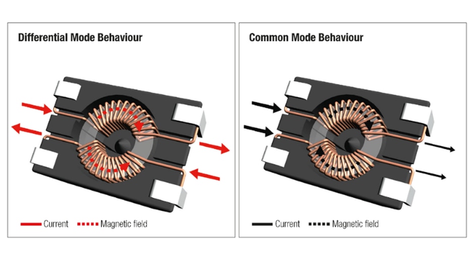
Figure 3. Common mode vs. Differential signals
The red arrows represent a differential signal going in. This is the useful signal. It creates a magnetic field inside the core going in one direction, according to the right-hand rule.
The differential signal then goes back to the source, which creates another magnetic field, according to the right-hand rule. These two fields will cancel each other in the core.
Common mode noise also creates a magnetic flux inside the core, but this time both noise signals are in the same direction, as shown here by the black arrows resulting in the magnetic fields adding together. The core will response with high impedance to the unwanted noise.
When the Signal Will Be Attenuated
Something to keep in mind when using a common mode filter is that there will be a differential impedance that could attenuate the useful signal. As shown in the graph in Figure 6, the blue line represents the common mode impedance, and the red dotted line shows the differential impedance.
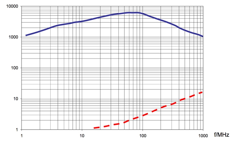
Figure 6. Common mode and differential impedance of a typical common mode inductor.
This means if the signal is at 100 MHz, using this common mode solution, there will be some unintentional attenuation of the signal from the differential impedance.
The Best Solution to Filter Noise Close to Signal Frequency
Here is a specific example. The blue line represents the common mode impedance, and the red dotted line shows the differential mode impedance. The useful signal is shown by the thick black line right at 4 MHz.
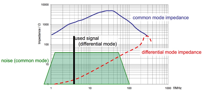
Figure 7. Avoiding impact on useful signal
This is making good use of the common mode chokes, with a high common mode impedance right at that 4 MHz and a low differential mode impedance.
Therefore, the impact on the noise is high, and the impact on the useful signal is kept to a minimum. When reading the datasheets, check both the common mode impedance and the differential mode impedance for that part.
Sectional vs. Bifilar Windings
There are two types of windings used in a common mode choke: sectional and bifilar.
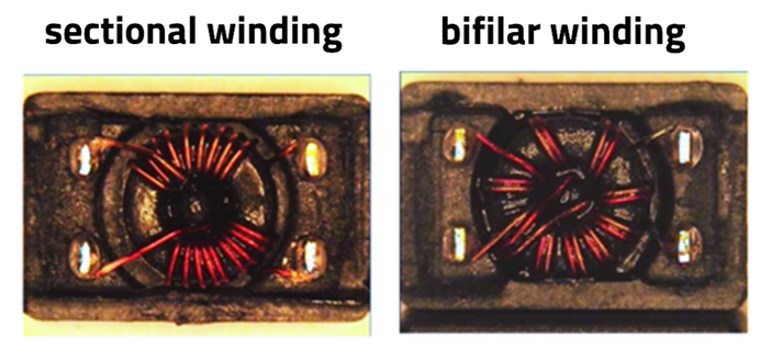
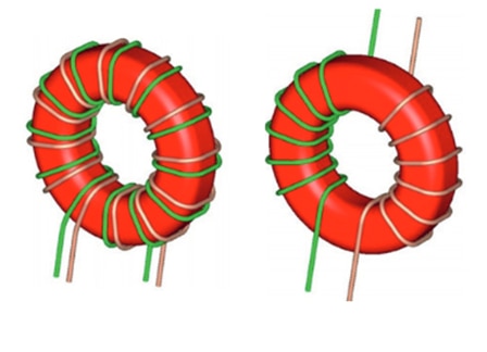
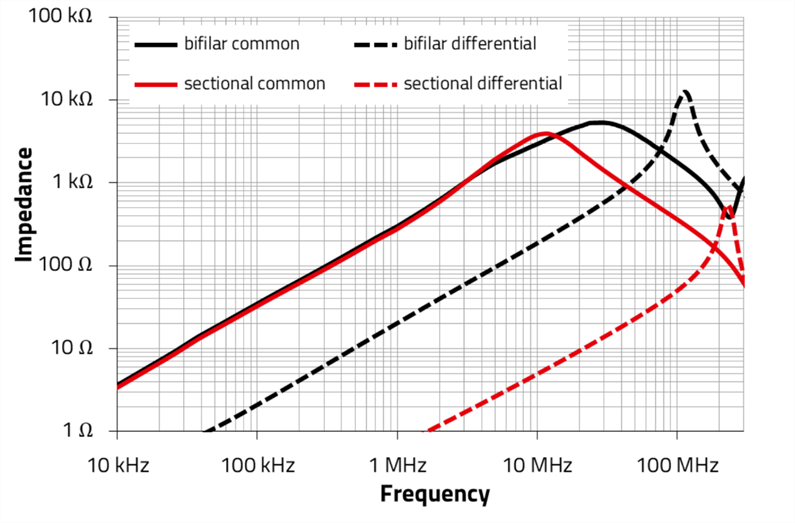
Figure 8. Sectional vs. Bifilar Winding
Sectional-wound components are most useful in power supply applications because high voltage lines must be separated by a minimum distance. They can also be used as inductors to attenuate differential mode noise. Because sectional components have a higher leakage inductance, they attenuate differential mode noise as well as common mode noise.
Bifilar-wound parts are typically used for low voltage data signal lines because we don't want to attenuate the differential mode signal (useful signal). Thus, you have a lower leakage inductance, and that is utilized for filtering noise on a signal.
To summarize, the way either parts attenuate common mode noise is very similar. However, there’s a big difference between sectional-wound and bifilar-wound parts when it comes to differential mode noise attenuation.
You can see these differences shown with the red and black lines Figure 8. Notice that the common mode impedance (solid lines) are very similar, whereas the differential mode impedance (dashed lines) are very different.
CMC Selection via REDEXPERT
Würth Elektronik’s online tool REDEXPERT can help you find the right components to attenuate noise. Use REDEXPERT’s EMI Filter Designer to help design and visualize the results. Simply enter the details of the system and the noise you are looking to attenuate in order to find the proper components.
By understanding the difference between common mode and differential noise, as well as how to use common mode chokes, you will be able to reduce unwanted noise in your designs. Our next article will provide even more information on differential noise and chip bead ferrites, so be on the lookout to keep improving your EMC knowledge!
In the meantime, our previous articles on EMI Basics and EMC Losses are also available.
