Isolated MagI³C Power Module Mastering the 24V Industry Bus
Maximum Input Voltage – Upper Limit
Author: Timur Uludag / Editor: Gerhard Stelzer
In the industrial environment, 24 V bus systems are widely used to supply a wide range of field devices. The article series so far explained selection criteria for power modules, typical voltage ranges, the issues with input voltage limits and especially the lower limit of the minimum input voltage. Part 4 focusses on the upper limit of the maximum input voltage.
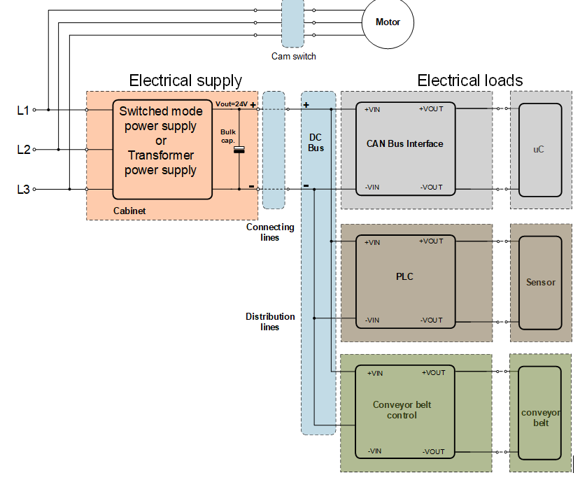
For the derivation of the maximum input voltage, the industrial plant (figure 1) has to be decomposed to its functional units, which are the electrical grid, the DC bus and the electrical loads. The electrical supply itself, e.g. transformer power supply without post regulation, is going to be supplied with 3x380Vac -15% / +20% whereby it is possible that the DC bus voltage differs from the nominal 24V. Furthermore voltage fluctuations of the AC input voltage due to relieved AC motors that are connected in parallel change the output voltage of a transformer power supply.
As already mentioned, the supply and the loads are connected through a DC bus, with some 10 meters cable connections. These cables can act as an antenna and receive disturbances from neighboring pulse loads such as frequency converters. These disturbances can then be distributed to the entire DC bus and every connected application. In addition, the input side physical connection of the different applications itself through the DC bus could lead to interactions. These include voltage spikes due to induced switching transients and back feeding overvoltage from DC motors. As a basis for the explanation of the maximum input voltage value two parameters are relevant:
First, the value of the maximum output voltage of the electrical power supply that is technically possible. Second, the maximum peak value of an input protection element for a nominal 24V application.

Figure 1. Typical industrial set-up of power supplies.
Every switched mode power supply or transformer power supply has one or more output electrolytic capacitors for stabilization and filtering the output voltage (figure 1). These capacitors have a voltage rating of 35V for a 24V nominal output voltage. The IEC 60384-4, chapter 4.14 defines peak voltages and their frequency for the lifetime of an electrolytic capacitor that can be applied without visible damages of the capacitor or a capacitance change of less than 15%. The bearable peak voltage is set to the 1.15 times of the rated voltage. This leads to 40.25V for a 35V capacitor.
To protect the input of the application against transient overvoltages, Transient Voltage Suppressor Diodes (TVS) are commonly used. The diode conducts if the breakdown voltage VBR is reached and the energy of the impulse is bypassed through the diode and thus protects the load. No destructive voltage greater than the clamping voltage VClamp of the TVS can be present.
To protect a 24V application against transients, following basic guideline might be a suitable reference point:
The diode starts conducting at the maximum reverse voltage (VRMW) and the current is negligible with only few µA. Therefore, the nominal operating voltage of the load and its tolerances has to be above VRMW. For a nominal 24V rail, a TVS diode from Würth Elektronik with 26V VRMW is a common value. When the transient voltage reaches VBR the diode conducts and a current of 1mA is flowing.
Due to the technology of a TVS diode, the breakdown voltage has a tolerance between a minimum and maximum value. Therefore a precise tripping point cannot be defined. For our 26V VRMW example we have the region between 28.9V and 31.9V. The diode is able to clamp the maximum voltage VClamp while conducting the maximum allowable current of IPeak. For a TVS diode with a 26V reverse voltage VRMW the clamping voltage VClamp is typically 42.1V. If you compare TVS diodes from various suppliers the characteristic values are all nearly in the same range.
The TVS diode protects a DC/DC power module in the 24V system against overshoots above the absolute maximum ratings VINMAX. In general the higher this value is specified the easier it is to design the right TVS diode and the input filter. That means that it is more difficult to find the right diode if the nominal operating input voltage is close to the maximum input voltage VINMAX of the module.
In conclusion, a specification of the maximum operating input voltage VIN of the SIP-8 isolated power module, 42V is a proper value to withstand the 40.25V and 42.1V transients as shown above.
This article series is being continued with “Power Boost Feature”.

