


Application Note
REDCUBE PRESS- FIT Terminals for automotive applications
SN025 by Markus Stark
1. THE PRESS-FIT TECHNOLOGY
REDCUBE PRESS-FIT terminals stand out as the go-to choice for robust high-power connections at the PCB level in automotive applications. They're widely employed for connecting wiring with cable lugs to circuit boards. The current rating of REDCUBE PRESS-FIT is seriously impressive. Even with the same power output, these components generate the least amount of heat compared to alternatives for powering PCBs.
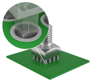
Figure 1: PRESS-FIT Technology.
By pressing the pins directly into the PCB, there's a strong friction between the pin and the plated through-hole, creating a seamless cold-welding connection between the pin and the copper-plated via within the PCB. This delivers a secure, gastight, and mechanically strong connection with a contact resistance of less than 200 µOhm. No other technology matches the ability to handle currents up to 250 A with such minimal self-heating.
In terms of long-term reliability, REDCUBE PRESS-FIT surpasses a surface-mount technology (SMT) solder joint by up to 30 times. A single solid press pin typically requires a force of 100 N to extract it from a 1.6 mm PCB.
So, even a small component with 8 pins could handle the weight of an average person without being pulled out of the PCB. This makes REDCUBE PRESS-FIT Terminals ideal for offering both electrical and mechanical connection solutions for electronic components. If after pressing the connector into the printed circuit board, the solid press pin interference on each of the four corners is greater than 3° against the via sleeve, the press connection zone exhibits lower electrical resistance than the brass pin itself. This ensures there's no electrical or thermal bottleneck. The example in Figure 2 shows a cross-section of the pressed pin in the via. Typically, the connection surface angle is significantly larger, offering ample safety margin for the electrical connection.

Figure 2: Required connection angle only 3°.
The 3° refers to the to a portion of a full circle’s 360° At the same time, this area should not exceed 12°, otherwise, the via copper plating can be damaged. The values specified in the data sheet ensure compliance with this requirement.
Press-fit technology offers several advantages over solder technology. It's particularly adept at handling very thick circuit boards with heavy copper plating. Additionally, it allows for trouble-free two-sided mounting of circuit boards, facilitating compact module designs.
With Press-fit technology, there's consistent contact between the pin and the copper layer along the entire length of the press-fit zone. This reliability is not assured with soldering, as solder may not fully rise along the entire length of the via, leading to increased transition resistances.
Consequently, the long-term reliability and mechanical stability are not as robust as with REDCUBE PRESS-FIT. Unlike soldering, this process does not subject the circuit boards to thermal loading.
REDCUBE PRESS-FIT connectors from Würth Elektronik are crafted from CuZn39Pb3 material, ensuring they comply with RoHS standards regarding copper alloys.
2. THE APPLICATION
As already mentioned, REDCUBE PRESS-FIT Terminals are capable of carrying currents exceeding 250 A on the circuit board.
However, it's crucial to evaluate the current-carrying capacity of REDCUBE PRESS-FIT within the context of the entire system. Factors such as conductor path thickness, width, cable cross-section, ambient temperature, and heat distribution must all be carefully considered when selecting the appropriate REDCUBE PRESS-FIT terminals for the application.
The press-fit zone itself exhibits extremely low resistance, ranging from 100 to 200 µOhm. As a result, the limiting factor often arises from the layout of the connected conductor paths or the connection of external feed lines to a press-fitted component.
Indeed, the challenge in designing high-current applications lies in achieving the optimal interaction among all components of the system.
3. THE PROCESSING
Hot Air Leveling (HAL) as well as electroless nickel immersion gold (ENIG) PCBs are not recommended to use. HAL surfaces are inhomogeneous and reliable contacting across all layers cannot always be guaranteed. ENIG surfaces are very hard and brittle. This can lead to chip formation on the pin or to contact problems with the PCB in conjunction with the existing nickel layer.
Immersion-coated PCB surface finishes, on the other hand, ensure even distribution of tin throughout the via hole. This makes it easier to meet tolerances and effectively prevents chip formation. Chips (plating or solder pushed out of the via) can affect the technical cleanliness of the system and, although rather unlikely, can lead to short circuits as a conductive particle. REDCUBE PRESS-FIT Terminals feature square-shaped press-fit pins. The design specifications for the through-hole are outlined in the respective specifications and must be adhered to.
For optimal performance with a standard REDCUBE PRESSFIT, the circuit board thickness should ideally fall within the range of 1.6 to 2.7 mm. The typical extraction force is approximately 100 N per pin for a PCB thickness of 1.6 mm. Greater circuit board thicknesses correspond to correspondingly higher values.
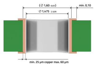
Figure 3: Specification for chemical surfaces.
Mounting a copper rail to increase the current-carrying capacity is also achievable with REDCUBE PRESS-FIT terminals. This can be done in two ways: by press-fitting the copper rail beneath the circuit board or by screwing it onto the REDCUBE PRESS-FIT. During the press-fit process, it's important to ensure that the maximum overall thickness of the circuit board with the copper rail does not exceed 2.7 mm.
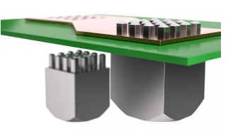
Figure 4: Pressing process: PCB directly with copper bar.
Furthermore, REDCUBE PRESS-FIT terminals are ideally suited for fulfilling purely mechanical functions, such as connecting circuit boards to cases or linking two circuit boards together.
4. THE DESIGN HINTS
- Other components should be mounted at least 4 mm from the press-fit hole due to slight PCB flexing during insertion.
- The press-fit hole should have a minimum distance of 3 mm from the edge.
- The press-fit force per pin should range from a minimum of 40 N to a maximum of 250 N. Typically, for a 1.6 mm PCB, this force falls around 100-150 N per pin. The exact values can be found in the respective datasheet.
- During the entire press-fit process, it's essential to support the press-fit zone. Without proper support, there's a risk of circuit board deflection during pressing. This is especially crucial for pneumatic presses, where it's important to ensure that the stroke cycle is performed evenly and consistently. 3D printed or aluminum supporters are only suitable for a few samples.
- The stroke cycle should be executed in one movement perpendicular and without angular misalignment to the PCB. This prevents defects in the via or delamination of the printed circuit board. Following press-fitting, the pins should slightly protrude from the circuit board and no components should press against them. The recommend minimum separation is 0.1 mm.
- Our REDCUBE PRESS-FIT terminals are specifically designed for press fitting. Alternative processing methods, such as soldering, are not recommended. Due to their high heat absorption, press-fitting of the REDCUBE PRESS-FIT should be carried out last, after all soldering processes are completed.
- Re-soldering REDCUBE PRESS-FIT terminals after the press-fit process is also not recommended. Re-soldering can potentially lead to partial destruction of the cold weld and delamination in the circuit board, resulting in the permanent loss of mechanical stability in the pressfit zone.
- To prevent mechanical damage to the REDCUBE PRESSFIT and the PCB, it's crucial to adhere to the maximum permissible torques. The exact values can be found in the respective datasheet.
- The force-fitting speed shall be a maximum of 250 mm/min.
IMPORTANT NOTICE
The Application Note is based on our knowledge and experience of typical requirements concerning these areas. It serves as general guidance and should not be construed as a commitment for the suitability for customer applications by Würth Elektronik eiSos GmbH & Co. KG. The information in the Application Note is subject to change without notice. This document and parts thereof must not be reproduced or copied without written permission, and contents thereof must not be imparted to a third party nor be used for any unauthorized purpose. Würth Elektronik eiSos GmbH & Co. KG and its subsidiaries and affiliates (WE) are not liable for application assistance of any kind. Customers may use WE’s assistance and product recommendations for their applications and design. The responsibility for the applicability and use of WE Products in a particular customer design is always solely within the authority of the customer. Due to this fact it is up to the customer to evaluate and investigate, where appropriate, and decide whether the device with the specific product characteristics described in the product specification is valid and suitable for the respective customer application or not. The technical specifications are stated in the current data sheet of the products. Therefore the customers shall use the data sheets and are cautioned to verify that data sheets are current. The current data sheets can be downloaded at www.we-online.com. Customers shall strictly observe any product-specific notes, cautions and warnings. WE reserves the right to make corrections, modifications, enhancements, improvements, and other changes to its products and services. WE DOES NOT WARRANT OR REPRESENT THAT ANY LICENSE, EITHER EXPRESS OR IMPLIED, IS GRANTED UNDER ANY PATENT RIGHT, COPYRIGHT, MASK WORK RIGHT, OR OTHER INTELLECTUAL PROPERTY RIGHT RELATING TO ANY COMBINATION, MACHINE, OR PROCESS IN WHICH WE PRODUCTS OR SERVICES ARE USED. INFORMATION PUBLISHED BY WE REGARDING THIRD-PARTY PRODUCTS OR SERVICES DOES NOT CONSTITUTE A LICENSE FROM WE TO USE SUCH PRODUCTS OR SERVICES OR A WARRANTY OR ENDORSEMENT THEREOF. WE products are not authorized for use in safety-critical applications, or where a failure of the product is reasonably expected to cause severe personal injury or death. Moreover, WE products are neither designed nor intended for use in areas such as military, aerospace, aviation, nuclear control, submarine, transportation (automotive control, train control, ship control), transportation signal, disaster prevention, medical, public information network etc. Customers shall inform WE about the intent of such usage before design-in stage. In certain customer applications requiring a very high level of safety and in which the malfunction or failure of an electronic component could endanger human life or health, customers must ensure that they have all necessary expertise in the safety and regulatory ramifications of their applications. Customers acknowledge and agree that they are solely responsible for all legal, regulatory and safety-related requirements concerning their products and any use of WE products in such safety-critical applications, notwithstanding any applications-related information or support that may be provided by WE. CUSTOMERS SHALL INDEMNIFY WE AGAINST ANY DAMAGES ARISING OUT OF THE USE OF WE PRODUCTS IN SUCH SAFETYCRITICAL APPLICATIONS.
DIRECT LINK
SN025 | REDCUBE PRESS- FIT Terminals for automotive applications
USEFUL LINKS:
Application Notes : https://we-online.com/en/support/knowledge/application-notes
Services: https://we-online.com/en/products/components/service
Contact : https://we-online.com/en/support/contact
CONTACT INFORMATION
Würth Elektronik eiSos GmbH & Co. KG
Max-Eyth-Str. 1, 74638 Waldenburg, Germany
Tel.: +49 (0) 7942 / 945 – 0
Email: appnotes@we-online.de
