

Support Note
How to Use Supercapacitors? A Brief Guide to the Design-In Process
SN009 BY DR. RENÉ KALBITZ / FRANK PUHANE
1 EDLC – Supercapacitor
Compared to other capacitor technologies, EDLCs (Electric Double Layer Capacitor) are outstanding for their very high charge storage capacity and very low equivalent series resistance (ESR). Their high cycle life, low charging time and their large power output make them the ideal choice for many electric power applications. Possible applications are:
(Intermediate) storage devices
- To provide an application with power during battery change or power-offline periods
- To provide power in emergency cases as uninterruptible power supplies (UPS)
Hybrid application with battery
- To relieve batteries during high power peak
- To buffer energy fluctuations in order to increase battery life time
The most important parameters for the design-in process are capacitance, discharging and charging time as well as the corresponding voltages. Below we present a summary of the most important formulas and provide examples of calculations.[1,2,3]
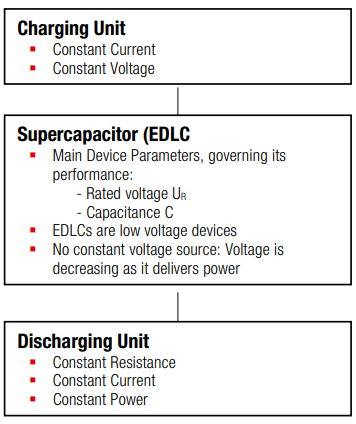
Figure 1: General concept of charging/discharging infrastructure.
2 General Procedure of Design-In
1st Identify the mode of operation for the discharge process:
- Constant Resistance
- Constant Current
- Constant Power
2nd Calculate*) the necessary capacitance depending on desired operation parameter such as operation time, output power and output current.
*) For the sake of simplicity we may neglect the losses due to ESR, leads and connections.
3nd Identify the suitable charging process:
- Constant Current
- Constant Voltage
4nd Calculate the charging time depending on the charging current. If necessary calculate the protective resistor.
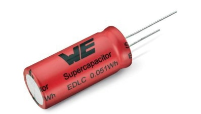
Figure 2: Radial through-hole EDLC series WCAP-STSC
Some important formulas for the design-in process are summarized in the following sections.
3 Parameter and Performance
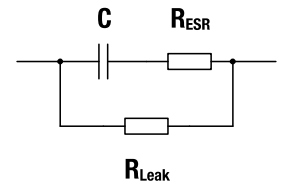
Figure 3: Equivalent Circuit of EDLC
Basic Parameters:
|
VR
|
rated voltage
|
| C | capacitance (given in the datasheet and directly on the capacitors marking) |
| RESR | equivalent series resistance (ESR) (given in the datasheet) |
|
RLeak
|
equivalent parallel resistance, leakage resistance
|
| P | power output, i.e. power consumption of application |
Performance Parameters:
| V1 | charging voltage, usually VR = V1 |
|
V2 |
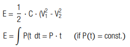
lower cut-off voltage energy storage capacity:
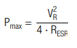
maximum power output:
|
3.1 Example
An application needs to be driven with a constant power of P = 0.4 W for t = 360 s. The lower cutoff voltage is V2 = 1 V. How large is the total amount of energy E and how large is the required capacitance C?
Calculation:
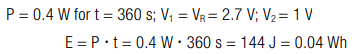
The required energy is E = 144 J
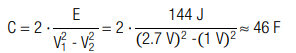
The required capacitance is C = 46 F, thus a capacitor with a capacitance of 50 F is recommended.
4 Constant Voltage Charging
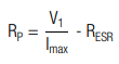
For constant voltage charging it is recommended to use a protective resistor in series with the EDLC. It may be necessary to restrict the current with a protective resistor RP to a specific value Imax. For a given Imax the resistance is calculated by:
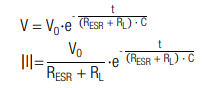
The charge characteristic is calculated by (t0 = 0):
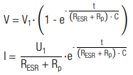
The corresponding charging time is calculated by:
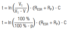
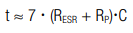
Charging to 99.9% :
| C | capacitance |
| V1 | charging voltage |
| I0 | current at t0 |
| Imax | max. allowable current |
| VR | rated voltage |
| V | voltage at t |
| t | charging time |
| t0 | start time |
| RP | protective resistance |
| RESR | equivalent series resistance |
| p | charging level in % |
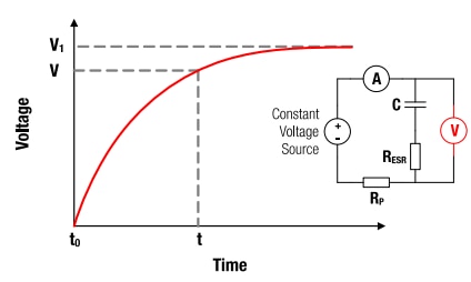
Figure 4: V-t characteristics for constant voltage charging
4.1 Example Protective Resistance
A capacitor with capacitance C = 50 F and an equivalent series resistance RESR = 0.02 Ω shall be charged with a unprotected power source at V1 = VR = 2.7 V. The power source has a maximal allowable current of Imax = 5 A. How large should the protective resistance be, to prevent overcurrent?
Calculation:
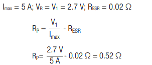
In order to prevent over current at the power source, a protective resistor with RP ≥ 0.52 Ω should be used.
4.2 Example Charging Time
A capacitor with capacitance C = 50 F is charged to V = 2.16 V (80 % of VR) at constant voltage VR = 2.7 V with a protective resistor RP = 0.5 Ω and an equivalent series resistance RESR = 0.02 Ω. How long is the charging process?
Calculation:
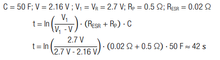
The charging time is ≈ 42 s.
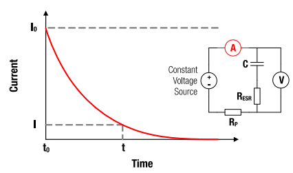
Figure 5: I-t characteristics for constant voltage charging
5 Constant Resistance Discharging
The discharging characteristics of a capacitor with capacitance C over given load resistance RL is calculated by (t0=0):
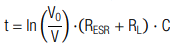
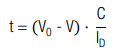
The corresponding discharging time is calculated by:
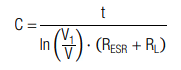
The necessary capacitance is calculated with:
| C | capacitance |
| V0 | charging voltage at t0 |
| I0 | current at t0 |
| V | voltage at t |
| t | discharging time |
| t0 | start time |
| RL | load resistance |
| RESR | equivalent series resistance |
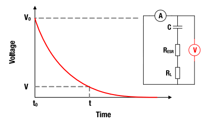
Figure 6: V-t characteristics for constant resistance discharging
5.1 Example Discharging Time
A capacitor with capacitance C = 50 F is discharged from its rated voltage VR = 2.7 V to V = 0.3 V with a load of RL = 1 Ω. How long is the discharging process?
Calculation:
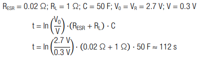
The discharge time is approximately 112 seconds.
5.2 Example Voltage Drop
A capacitor with a capacitance C = 50 F is discharged from its rated voltage VR = 2.7 V with a load of RL = 2 Ω for a period of time t = 280 s. What is the remaining voltage?
Calculation:
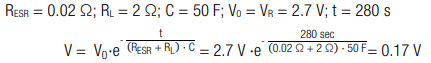
The remaining voltage is V = 0.17 V.
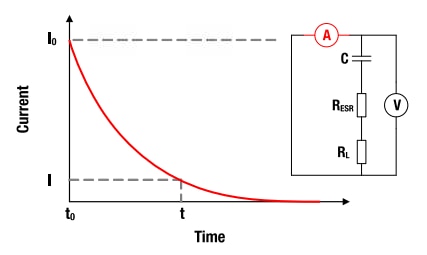
Figure 7: I-t characteristics for constant resistance discharging
6 Constant Current Charging/Discharging
If a constant current is used, the voltage V at the terminals for time t (t = 0) is calculated by:

The corresponding discharge time (t0 = 0) is calculated by:
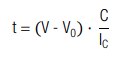
The corresponding charging time (t0 = 0) is calculated by:
The necessary capacitance is calculated with:

| I C,D | constant charge / discharge current |
| C | capacitance |
| VR | rated voltage |
| V, I | voltage, current at t |
| V0 | voltage at t0 (charging) |
| | t - t0 | | (dis)charge time |
| t0 | start time |
| R ESR | equivalent series resistance |
6.1 Example Charging Time
A capacitor with capacitance C = 50 F is charged from V0 = 0.3 V to its rated voltage VR = 2.7 V with a constant current IC = 2 A. How long is the charging process?
Calculation:
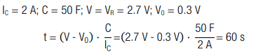
The charge time is 60 seconds.
6.2 Example Voltage Increase
A capacitor with capacitance C = 50 F and an initial voltage V0 = 0.3 V is charged with a constant current IC = 2 A for t = 5 s. How large is the capacitor voltage?
Calculation:
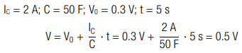
The capacitor voltage is V = 0.5 V.
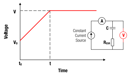
Figure 8: V-t characteristics for constant current charging.
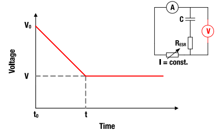
Figure 9: V-t characteristics for constant current discharging.
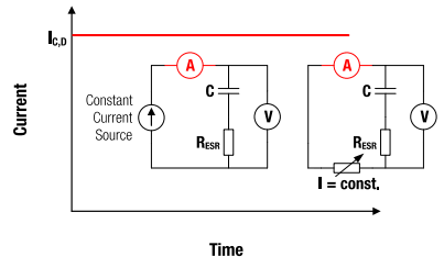
Figure 10: I-t characteristics for constant current charging and discharging.
7 Constant Power Discharging
If the capacitor is discharged at a constant power PC, the voltage and current characteristic are calculated by (t0 = 0):
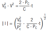
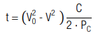
The corresponding discharge time (t0 = 0) is calculated by:
The necessary capacitance is calculated with:

| PC | constant power output |
| C | capacitance |
| VR | rated voltage |
| V, I | voltage, current at t |
| I0 | current at t0 |
| V0 | voltage at t0 (charging) |
| t - t0 | discharge time |
| t0 | start time |
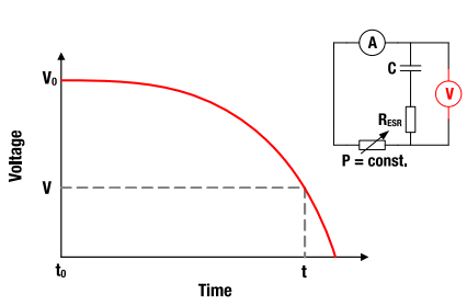
Figure 11: V-t characteristics for constant power discharging
7.1 Example Discharge Time
A capacitor with capacitance C = 50 F and rated voltage VR = 2.7 V is discharged at constant power PC = 0.2 W. The cut-off voltage is V = 0.7 V. How long can the capacitor be operated under this condition?
Calculation:
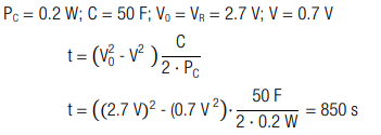
It can be operated for t = 850 s.
7.2 Example Voltage Drop
A fully charged capacitor with capacitance C = 50 F and rated voltage VR = 2.7 V has been operated for t = 180 s at constant power output of PC = 0.7 W. How large is the remaining voltage?
Calculation:
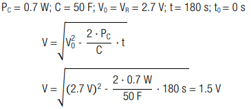
The remaining voltage is V = 1.5 V
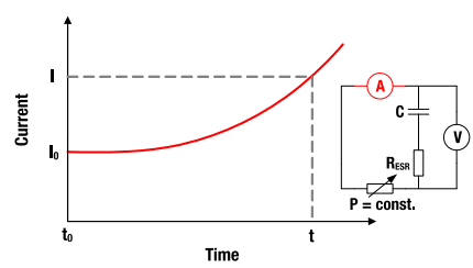
Figure 12: I-t characteristics for constant power discharging
A. Appendix
A.1. References
[1] N. Kularatna (2015). Energy Storage Devices for Electronic Systems – Rechargeable Batteries and Supercapacitors. Elsevier Academic Press (Print Book)
[2] F. Beguin, E. Frackowiak, G. Q. M. Lu (eds.) (2013). Supercapacitors - Materials, Systems, and Applications. Wiley-VCH (Print Book)
[3] B. E. Conwa (1999). Electrochemical Supercapacitors – Scientific Fundamentals and Technological Applications. Kluwer Academics / Plenum Publishers, New York (Print book)
IMPORTANT NOTICE
The Application Note is based on our knowledge and experience of typical requirements concerning these areas. It serves as general guidance and should not be construed as a commitment for the suitability for customer applications by Würth Elektronik eiSos GmbH & Co. KG. The information in the Application Note is subject to change without notice. This document and parts thereof must not be reproduced or copied without written permission, and contents thereof must not be imparted to a third party nor be used for any unauthorized purpose. Würth Elektronik eiSos GmbH & Co. KG and its subsidiaries and affiliates (WE) are not liable for application assistance of any kind. Customers may use WE’s assistance and product recommendations for their applications and design. The responsibility for the applicability and use of WE Products in a particular customer design is always solely within the authority of the customer. Due to this fact it is up to the customer to evaluate and investigate, where appropriate, and decide whether the device with the specific product characteristics described in the product specification is valid and suitable for the respective customer application or not. The technical specifications are stated in the current data sheet of the products. Therefore the customers shall use the data sheets and are cautioned to verify that data sheets are current. The current data sheets can be downloaded at www.we-online.com. Customers shall strictly observe any product-specific notes, cautions and warnings. WE reserves the right to make corrections, modifications, enhancements, improvements, and other changes to its products and services. WE DOES NOT WARRANT OR REPRESENT THAT ANY LICENSE, EITHER EXPRESS OR IMPLIED, IS GRANTED UNDER ANY PATENT RIGHT, COPYRIGHT, MASK WORK RIGHT, OR OTHER INTELLECTUAL PROPERTY RIGHT RELATING TO ANY COMBINATION, MACHINE, OR PROCESS IN WHICH WE PRODUCTS OR SERVICES ARE USED. INFORMATION PUBLISHED BY WE REGARDING THIRD-PARTY PRODUCTS OR SERVICES DOES NOT CONSTITUTE A LICENSE FROM WE TO USE SUCH PRODUCTS OR SERVICES OR A WARRANTY OR ENDORSEMENT THEREOF. WE products are not authorized for use in safety-critical applications, or where a failure of the product is reasonably expected to cause severe personal injury or death. Moreover, WE products are neither designed nor intended for use in areas such as military, aerospace, aviation, nuclear control, submarine, transportation (automotive control, train control, ship control), transportation signal, disaster prevention, medical, public information network etc. Customers shall inform WE about the intent of such usage before design-in stage. In certain customer applications requiring a very high level of safety and in which the malfunction or failure of an electronic component could endanger human life or health, customers must ensure that they have all necessary expertise in the safety and regulatory ramifications of their applications. Customers acknowledge and agree that they are solely responsible for all legal, regulatory and safety-related requirements concerning their products and any use of WE products in such safetycritical applications, notwithstanding any applications-related information or support that may be provided by WE. CUSTOMERS SHALL INDEMNIFY WE AGAINST ANY DAMAGES ARISING OUT OF THE USE OF WE PRODUCTS IN SUCH SAFETY-CRITICAL APPLICATIONS.
DIRECT LINK
SN009: How to use supercapacitors
USEFUL LINKS:
Application Notes : https://we-online.com/en/support/knowledge/application-notes
Services: https://we-online.com/en/products/components/service
Contact : https://we-online.com/en/support/contact
CONTACT INFORMATION
Würth Elektronik eiSos GmbH & Co. KG
Max-Eyth-Str. 1, 74638 Waldenburg, Germany
Tel.: +49 (0) 7942 / 945 – 0
Email: appnotes@we-online.de
Web: https://www.we-online.com