Support Note
Cracks on Molded Power Inductors
SN018 BY MOHAMED KOOBAR, TOBIAS FREI
1 Introduction
This document helps understanding the influence of visual asymmetry around the core which may occur during the manufacturing process of WE-LHMI series inductors. WE-LHMI series inductors have an optimized molding technology, especially designed for low profile high current applications like laptops, tablets, battery operated devices, etc. where the need for high current, high stability Point of Load devices are increasing.
The advantages of WE-LHMI series products are high saturation current which exhibits soft saturation characteristic, low core losses, high operating temperature, and a small footprint. Unlike most of the power inductor cores, WE-LHMI core is not a ferrite, it is a mixture of iron powder and resin binder which is pressed around the inductor coil. The resin binder creates a distributed gap and greatly enhances the electrical characteristics of an inductor. After pressing, the mixture is cured along with the inductor coil in an oven to increase the bonding strength between resin binders and iron powder. Unlike other manufacturers, WE-LHMI series products are coated with varnish to avoid oxidation around the core which can affect the realitibilty of the inductor.
2 Visual Appearance & Effects
It is desirable to have a good visual appearance. The manufacturing process involved in the molding process, as well as the physical properties of the core material have limitations in maintaining perfect visual appearance. This application note further explains the affects that can be seen.
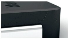
WE-LHMI series products with and without visual imperfections have passed all industry standard tests like thermal shock, mechanical shock, terminal strength, vibration, humidity, moisture resistance, operational life, etc. These imperfections do not affect the reliability or performance of WE-LHMI series products. Cracks around the core are nearly impossible to eliminate as the molding process involves curing the resin binder and iron powder together.
During the manufacturing process small scratches can be caused by surface friction when ejecting the component. Unlike in ferrite powder inductors, small to medium-sized cracks can occur in addition to the superficial scratches due to the above-mentioned different expansion behaviors of the materials. These are considered as optical appearances which have no influence on the performance of the WE-LHMI series. Würth Elektronik eiSos has internal standards to evaluate such cracks in order to guarantee consistently high quality and the specified electrical parameters according to the data sheet.
3 Cracks
Cracks and scratches that occur are categorized into acceptable and unacceptable. In order to create a better understanding of the assessment, the evaluation is based on ratios and not on absulote figures for quantifying the cracks and scratches.
Acceptable cracks
In general, cracks which are hard to recognise with the human eye, are acceptable.
Rejectable cracks
Cracks which are easy to identify with the human eye and that have a clear cut in the component are considered as rejectable. As soon as one side shows two cracks, the component is considered as rejectable.
Examples for assessment, top view
- Slight cracks, which are hard to recognize are considered as acceptable.
- Obvious cracks on the top side are rejectable
Acceptable cracks / scratches Rejectable cracks

Examples for assessment, side view without clip
- Cracks that are less or equal to 2/3 of the total length are considered as acceptable.
- Cracks which are obvious and longer than 2/3 of the total length are rejectable.
Acceptable cracks / scratches Rejectable cracks

Examples for assessment, side view with clip
- Cracks which extend around the corner and do not exceed 1/4 of the length of the adjacent side (not containing the clip) are acceptable.
- Cracks which are obvious, extend around the corner and exceed 1/4 of the total length of the adjacent side (not containing the clip) are rejectable.
Acceptable cracks / scratches Rejectable cracks

It can be possible that due to the different expansion coefficients of the materials, cracks may occur from the top corner during the curing process. This occurrence is considered as acceptable.
Acceptable cracks / scratches

Examples for assessment, bottom view
- Cracks, which do not exceed 2/3 of the total length, are considered as acceptable.
- The following cracks which are obvious and visually easy to identify are rejectable:
- Cracks extending from one clip to the other
- Cracks which exceed 2/3 of the total length
Acceptable cracks / scratches Rejectable cracks

4 Chip off
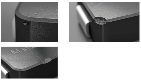
Chip off can occur through the handling of the components during the manufacturing-process. Even though the chip offs do not affect the function of the part until the coil is exposed or broken, Würth Elektronik eiSos has set up internal standards to evaluate the chip offs. The chipping typically occurs on the edges, surface and corners of the inductor:

Figure 1: Chip off at various locations
Excamples of acceptable and rejectable chip offs
Minor Chip offs on one surface or two surface junctions are acceptable.
Obvious chip offs on the edges (on three surfaces) are rejectable.
Acceptable chip off Rejectable chip off

5 Electrical performance
Several electrical and reliability tests were performed on WE-LHMI products with visual imperfections.Those tests have shown that these imperfections do not affect the reliability or performance of the products. The influence on the electrical parameters of a WE-LHMI with and without a 15% chipping in a typical application is compared in the following:
A synchronous step down switching regulator is implemented using an LTC3810 controller and a WE-LHMI 74437368068 inductor without visual imperfections.
The DCDC converter has the following specifications:
- 60 W power
- 250 kHz switching frequency
- 24 V input
- 12 V output at 5 A
The WE-LHMI 74437368068 with an inductance value of 6.8 μH inductor archieved following test results:
11.78 V, 5.02 A with 93 % efficiency.
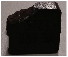
An approximate 15% chip was broken off the original inductor (please refer to figure 2) and the part was remeasured.

Figure 2: Broken edge on WE-LHMI 74437368068
This inductor achieved the same test results as the original part without chipping.
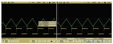
The waveforms of the inductors with and without chipping are shown in figure 3.

Figure 3: Waveform of the inductor current and switching voltage with inductance without visual features (left side) and with 15% chipping on the inductor core (right side)
The waveform in green is the current measured through the inductor using a Hall effect probe and the waveform in yellow is the voltage measured at the drain of the MOSFET.
The reasons for the consistant performance even with large, unacceptable cracks as well as chip offs are:
- The high flux density in the core only occurs in the closest area next to the windings
- The core material has a distributed "air gap" and the resulting lower relative permeability of the material drastically reduces the effect of discontinuities in the material (cracks).
- The magnetic cross sectional area on the sides of the inductor is much larger than the center therefore the flux density is lower. As demostrated, even with large chips, the flux can easy distribute to other areas without affecting performance.
6 Summary
In order to meet the requirements of modern electronic circuits, it is important to use a technology that offers stable inductance at high currents maintaining a compact design.The WE-LHMI core is not preformed, instead it is a mixture of binder and iron powder molded around the winding. The molding technology of composite materials offers many advantages for an inductor. However due to physics, it can bring some irregularities, but these do not affect the performance or the electrical parameters of the component specified in the data sheet.
IMPORTANT NOTICE
The Application Note is based on our knowledge and experience of typical requirements concerning these areas. It serves as general guidance and should not be construed as a commitment for the suitability for customer applications by Würth Elektronik eiSos GmbH & Co. KG. The information in the Application Note is subject to change without notice. This document and parts thereof must not be reproduced or copied without written permission, and contents thereof must not be imparted to a third party nor be used for any unauthorized purpose. Würth Elektronik eiSos GmbH & Co. KG and its subsidiaries and affiliates (WE) are not liable for application assistance of any kind. Customers may use WE’s assistance and product recommendations for their applications and design. The responsibility for the applicability and use of WE Products in a particular customer design is always solely within the authority of the customer. Due to this fact it is up to the customer to evaluate and investigate, where appropriate, and decide whether the device with the specific product characteristics described in the product specification is valid and suitable for the respective customer application or not. The technical specifications are stated in the current data sheet of the products. Therefore the customers shall use the data sheets and are cautioned to verify that data sheets are current. The current data sheets can be downloaded at www.we-online.com. Customers shall strictly observe any product-specific notes, cautions and warnings. WE reserves the right to make corrections, modifications, enhancements, improvements, and other changes to its products and services. WE DOES NOT WARRANT OR REPRESENT THAT ANY LICENSE, EITHER EXPRESS OR IMPLIED, IS GRANTED UNDER ANY PATENT RIGHT, COPYRIGHT, MASK WORK RIGHT, OR OTHER INTELLECTUAL PROPERTY RIGHT RELATING TO ANY COMBINATION, MACHINE, OR PROCESS IN WHICH WE PRODUCTS OR SERVICES ARE USED. INFORMATION PUBLISHED BY WE REGARDING THIRD-PARTY PRODUCTS OR SERVICES DOES NOT CONSTITUTE A LICENSE FROM WE TO USE SUCH PRODUCTS OR SERVICES OR A WARRANTY OR ENDORSEMENT THEREOF. WE products are not authorized for use in safety-critical applications, or where a failure of the product is reasonably expected to cause severe personal injury or death. Moreover, WE products are neither designed nor intended for use in areas such as military, aerospace, aviation, nuclear control, submarine, transportation (automotive control, train control, ship control), transportation signal, disaster prevention, medical, public information network etc. Customers shall inform WE about the intent of such usage before design-in stage. In certain customer applications requiring a very high level of safety and in which the malfunction or failure of an electronic component could endanger human life or health, customers must ensure that they have all necessary expertise in the safety and regulatory ramifications of their applications. Customers acknowledge and agree that they are solely responsible for all legal, regulatory and safety-related requirements concerning their products and any use of WE products in such safetycritical applications, notwithstanding any applications-related information or support that may be provided by WE. CUSTOMERS SHALL INDEMNIFY WE AGAINST ANY DAMAGES ARISING OUT OF THE USE OF WE PRODUCTS IN SUCH SAFETY-CRITICAL APPLICATIONS.
DIRECT LINK
SN018: Cracks on Molded Power Inductors
USEFUL LINKS:
Application Notes : https://we-online.com/en/support/knowledge/application-notes
Services: https://we-online.com/en/products/components/service
Contact : https://we-online.com/en/support/contact
CONTACT INFORMATION
Würth Elektronik eiSos GmbH & Co. KG
Max-Eyth-Str. 1, 74638 Waldenburg, Germany
Tel.: +49 (0) 7942 / 945 – 0
Email: appnotes@we-online.de
Web: https://www.we-online.com
