Wireless M-bus
Introduction

Wireless M-Bus
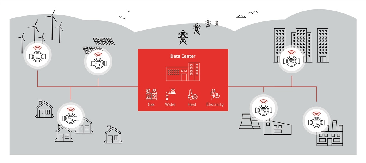
Wireless Meter Bus (wM-BUS) is the extension of the meter Bus (M-BUS) with a wireless protocol and role scheme for handling communication over a standardized wireless communication interface between meters and data loggers – so called smart meter gateways (SMGW). This scheme is specified by the European standard EN 13757 and its sub-standards. The motivation of this standard is to allow an automated measuring and processing of data, track the usage of resources and to optimize provisioning in order to create an “Advanced Metering Infrastructure” (AMI).
Such Smart grid / meter devices are typically battery operated and in need for a long range and robust wireless communication. This is the reason for using the Sub GHz frequencies in the free ISM Bands. EN13757-4 is specifying radio options in the 169 MHz, 434 MHz or 868 MHz band, regarding to the region.
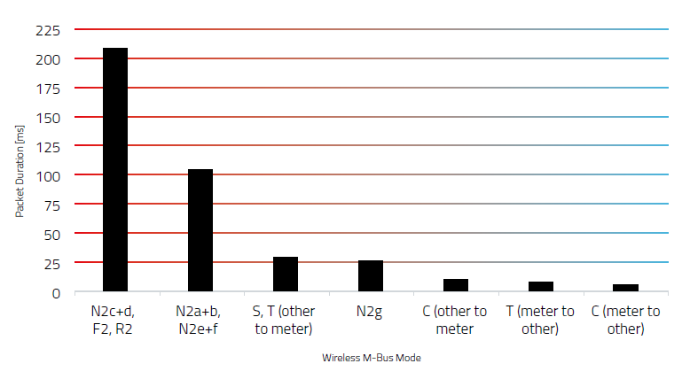
In between those frequencies there are different modes with different functions. In the table below you can see those specifications.

Uni- / Bidirectional
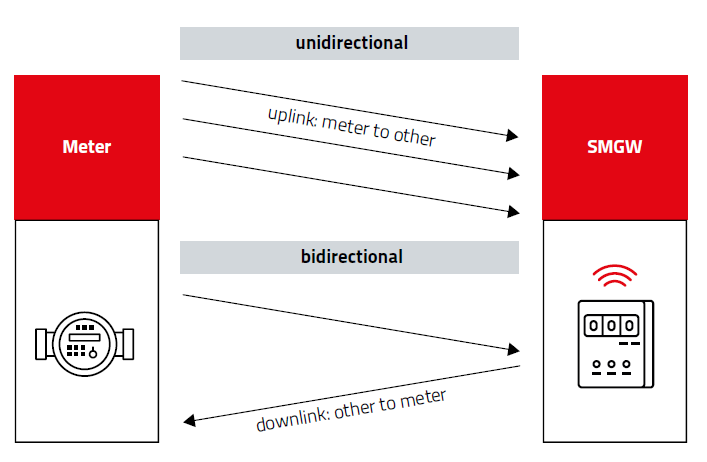
The wireless M-Bus (EN13757-4) differentiates the transfer in a network in 2 directions: uplink and downlink. Where uplink is used when a “meter” device sends data to a gateway (“other”) and downlink is used when a gateway (“other”) sends data to a “meter”. These two directions are, depending on the wireless M-Bus mode, either symmetric (S and N modes) or asymmetric (T and C modes). Where symmetric means that the same radio parameters (radio data rate, coding, modulation, frequency) are used for both directions – uplink and downlink. On the other hand, asymmetric means that those radio parameters are different.
A wireless M-Bus mode labeled with a '1' in the name (e.g. C1 meter) indicates that the device is a sender only and will not receive any radio frames. Whereas a wM-BUS mode with a '2' in the name (e.g. C2-other) means the device can operate as sender and receiver.
The ‘sender only’ mode of operation, such as C1 meter, is suitable for battery-operated meters that do not require any information in the downlink direction. These meters are usually designed to operate for at least 10 years with the integrated battery. Currently, the majority of smart meters utilize the C mode, specifically the C1 meter mode.
Data collectors or gateways typically receive T and C mode meter frames in a single mode of operation. This is possible since both physical layers only differ in the coding.

Payload
The payload of a wireless M-Bus frame is coded according to EN13757-3. Any meter reading value is located in one data block and the frame can contain one or multiple of such blocks. This allows the meter reading values to be transferred efficiently and in a well-defined yet flexible manner to provide interoperability. The drawback of this is, that the raw data of a wM-BUS frame is not readable for a human without parsing the data back into a readable format.

Different “Standards” in Europe

If you want to read more find here the whole Product Guide.

