element14 Community
element14 Community
    Register Log In
  • Site
  • Search
  • Log In Register
  • Community Hub
    Community Hub
    • What's New on element14
    • Feedback and Support
    • Benefits of Membership
    • Personal Blogs
    • Members Area
    • Achievement Levels
  • Learn
    Learn
    • Ask an Expert
    • eBooks
    • element14 presents
    • Learning Center
    • Tech Spotlight
    • STEM Academy
    • Webinars, Training and Events
    • Learning Groups
  • Technologies
    Technologies
    • 3D Printing
    • FPGA
    • Industrial Automation
    • Internet of Things
    • Power & Energy
    • Sensors
    • Technology Groups
  • Challenges & Projects
    Challenges & Projects
    • Design Challenges
    • element14 presents Projects
    • Project14
    • Arduino Projects
    • Raspberry Pi Projects
    • Project Groups
  • Products
    Products
    • Arduino
    • Avnet Boards Community
    • Dev Tools
    • Manufacturers
    • Multicomp Pro
    • Product Groups
    • Raspberry Pi
    • RoadTests & Reviews
  • Store
    Store
    • Visit Your Store
    • Choose another store...
      • Europe
      •  Austria (German)
      •  Belgium (Dutch, French)
      •  Bulgaria (Bulgarian)
      •  Czech Republic (Czech)
      •  Denmark (Danish)
      •  Estonia (Estonian)
      •  Finland (Finnish)
      •  France (French)
      •  Germany (German)
      •  Hungary (Hungarian)
      •  Ireland
      •  Israel
      •  Italy (Italian)
      •  Latvia (Latvian)
      •  
      •  Lithuania (Lithuanian)
      •  Netherlands (Dutch)
      •  Norway (Norwegian)
      •  Poland (Polish)
      •  Portugal (Portuguese)
      •  Romania (Romanian)
      •  Russia (Russian)
      •  Slovakia (Slovak)
      •  Slovenia (Slovenian)
      •  Spain (Spanish)
      •  Sweden (Swedish)
      •  Switzerland(German, French)
      •  Turkey (Turkish)
      •  United Kingdom
      • Asia Pacific
      •  Australia
      •  China
      •  Hong Kong
      •  India
      •  Korea (Korean)
      •  Malaysia
      •  New Zealand
      •  Philippines
      •  Singapore
      •  Taiwan
      •  Thailand (Thai)
      • Americas
      •  Brazil (Portuguese)
      •  Canada
      •  Mexico (Spanish)
      •  United States
      Can't find the country/region you're looking for? Visit our export site or find a local distributor.
  • Translate
  • Profile
  • Settings
Würth Elektronik
  • Products
  • Manufacturers
  • Würth Elektronik
  • More
  • Cancel
Würth Elektronik
Forum 100BASE-T1 PoDL Coupled inductor
  • Blog
  • Forum
  • Documents
  • Events
  • Polls
  • Files
  • Members
  • Mentions
  • Sub-Groups
  • Tags
  • More
  • Cancel
  • New
Join Würth Elektronik to participate - click to join for free!
Actions
  • Share
  • More
  • Cancel
Forum Thread Details
  • Replies 13 replies
  • Subscribers 69 subscribers
  • Views 3102 views
  • Users 0 members are here
  • inductor
  • wurth_elektronik
Related

100BASE-T1 PoDL Coupled inductor

Taip
Taip over 2 years ago

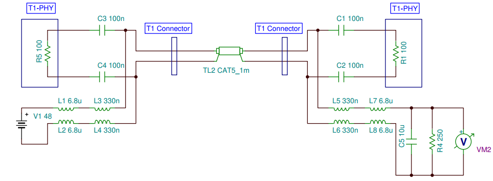
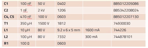
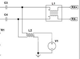
I am seeking advices for the values/part numbers for the DMI for filtering the power lines for the 100BASE-T1 PoDL with capacitive coupling in an engineering environment.  I am using a pair of the Microchip Eval boards https://www.microchip.com/en-us/development-tool/EV02N47A and add the filter and DMI suggested by TI's app note https://www.ti.com/lit/pdf/tiduet1 . The paper calls out the Wurth's cross-polarity coupled inductor 7448991068 (6.8uH) and 330nH inductors.

When I inserted the contraption the Link got lost. I traced back and the DMI is the part that killed the link. Researching on different paper, I think the value of 6.8uH for the DMI is too low, but I am not sure what is the right value to go with. I only need about 500mA at 12V to be transfered over the T1 line.

Thanks in advance for your help!

 image

  • Sign in to reply
  • Cancel

Top Replies

  • nwieland
    nwieland over 2 years ago +2
    Hi Taip , we made serveral tests and simulation regarding 100Base-T with PoDL. To fulfill the limits of the 802.3bw (mode conversion & return loss) we recommend this frontend setup as below. But we…
  • dougw
    dougw over 2 years ago

    There is a Wurth group on the forum if you want the manufacturer to chime in...

     Würth Elektronik 

    It is a bit odd that there doesn't seem to be a TI group.

    • Cancel
    • Vote Up 0 Vote Down
    • Sign in to reply
    • Cancel
  • nwieland
    nwieland over 2 years ago

    Hi Taip ,

    thank you for your question. I will forward your question to a colleague and get back to you with an answer.

    Best regards,

    Nicola

    Würth Elektronik

    • Cancel
    • Vote Up 0 Vote Down
    • Sign in to reply
    • Cancel
  • nwieland
    nwieland over 2 years ago

    Hi Taip ,

    we made serveral tests and simulation regarding 100Base-T with PoDL. To fulfill the limits of the 802.3bw (mode conversion & return loss)  we recommend this frontend setup as below.

    But we also investigated, that the inductance value of L2 can also be lower than 100uH. But we cannot recommend lower than 47uH.

    image

    Suitable double chokes for 500mA are:

    300nH à 744894300033 Datasheet WE-TDC SMT Shielded Coupled Inductor (we-online.com) or 74479762133 Datasheet WE-PMI Power Multilayer Inductor (we-online.com)

    47uH à 744878470 Datasheet WE-DD SMT Shielded Coupled Inductor (we-online.com)

    100uH à 744877101 Datasheet WE-DD SMT Shielded Coupled Inductor (we-online.com)

    Best Regards

    • Cancel
    • Vote Up +2 Vote Down
    • Sign in to reply
    • Cancel
  • Taip
    Taip over 2 years ago in reply to nwieland

    Nicola,

    Thank you very much for the details. Please help me understand the notations of the circuit. Are the TX+/- on the left from the PHY, or are they from the far end T1 line with PoDL?  L1 (10uH) in the Evals of both Microchip's and Ti's are 200uH, do I need to change htem to 10uH for it to work with L2 (100uH)? Can I use the same component values on both PSE and PD?

    Thank you very much for your help.

    Best regards,

    Tai

    image

    • Cancel
    • Vote Up 0 Vote Down
    • Sign in to reply
    • Cancel
  • nwieland
    nwieland over 2 years ago in reply to Taip

    Hi Taip ,


    the left side is directed tot he PHY. We have different inductance values of the CMC because we don’t use the 100nF but the transformator T1 for to achieve the 1,5kV insulation which is required for industrial applications. The T1 itself provide extra common mode rejection, therefore the CMC can be smaller. This solution is more elegant than using 100nF/2kV MLCCs .


    If you only need the 50V 100nF MLCC like in automotive applications it´s a different story.


    Usually you can use the same circuit for PSE and PD

     image

    • Cancel
    • Vote Up 0 Vote Down
    • Sign in to reply
    • Cancel
  • Taip
    Taip over 2 years ago in reply to nwieland

    Nicola,

    Thank you very much for the clarification. I will order the parts and wire up the prototypes. Will let you know once I have it done.

    Regards,

    Tai

    • Cancel
    • Vote Up 0 Vote Down
    • Sign in to reply
    • Cancel
  • Taip
    Taip over 2 years ago in reply to Taip

    Nicola,

    Actually, since this is a closed, engineered system, we don't need to stay with the 1.5kV isolation. Do you have suggestions on components if we want to stay with the simple 50V 100nF MLCC?

    Thanks,

    Tai

    • Cancel
    • Vote Up 0 Vote Down
    • Sign in to reply
    • Cancel
  • nwieland
    nwieland over 2 years ago in reply to Taip

    Hi Taip ,

    you can use the 885012206095 in the size 0603 or if you want to have a robust component the 885012207098 as 0805.

    • Cancel
    • Vote Up 0 Vote Down
    • Sign in to reply
    • Cancel
  • Taip
    Taip over 2 years ago in reply to nwieland

    Nicola, 

    I am sorry I did not ask my question clearly. What I want to know is if I want to stay with the 100nF capacitive coupling - No T1. Can I still use the same L1 and L2 suggested in this table? 

    image

     image

    • Cancel
    • Vote Up 0 Vote Down
    • Sign in to reply
    • Cancel
  • nwieland
    nwieland over 2 years ago in reply to Taip

    Hi Taip,

    if you want to use the 100nF/50V you should stay at the recommendations in the TI Ref Design. Sure with your lower current, we must adjust the size of the components:

    CMC(no PoDL current through it): 744235251 Datasheet WE-CNSW SMT Common Mode Line Filter (we-online.com)

    6,8µH: 7448841068 Datasheet WE-DPC HV SMT Dual Powerchoke (we-online.com) or  7448844068 Datasheet WE-DPC SMT Dual Powerchoke (we-online.com)

    330nH: 744894300033 Datasheet WE-TDC SMT Shielded Coupled Inductor (we-online.com) or 2x 74479762133 Datasheet WE-PMI Power Multilayer Inductor (we-online.com)

    TVS(super low capacitance): 824012823 Datasheet WE-TVS TVS Diode – Super Speed Series (we-online.com)

    • Cancel
    • Vote Up 0 Vote Down
    • Sign in to reply
    • Cancel
>
element14 Community

element14 is the first online community specifically for engineers. Connect with your peers and get expert answers to your questions.

  • Members
  • Learn
  • Technologies
  • Challenges & Projects
  • Products
  • Store
  • About Us
  • Feedback & Support
  • FAQs
  • Terms of Use
  • Privacy Policy
  • Legal and Copyright Notices
  • Sitemap
  • Cookies

An Avnet Company © 2025 Premier Farnell Limited. All Rights Reserved.

Premier Farnell Ltd, registered in England and Wales (no 00876412), registered office: Farnell House, Forge Lane, Leeds LS12 2NE.

ICP 备案号 10220084.

Follow element14

  • X
  • Facebook
  • linkedin
  • YouTube