


|
The Pico has a set of PIO co-processors. They are real-time controllers that can execute logic with deterministic timing. Ideal to run strict-timed sequences and state machines. And to implement extra peripherals.
|
PIO controllers are tiny and specialised. Focused on running a limited set of instructions with predictable timing. One of the things that add to the - rather steep - learning curve: they can't be debugged.
There is a solution. Jürgen Reuter developed an emulator. You can load your design and step through the code. At the same time, you can see what happens with the registers, and how GPIO pins behave during the execution. You can also set registers, read and write the FIFOs, move the program counter.
I've used it to verify a stepper motor controller that I wrote for PIO (source). And it's really useful to see how your program actually works. In stead of double guessing and trial & error - I did a lot of that when writing my first design.
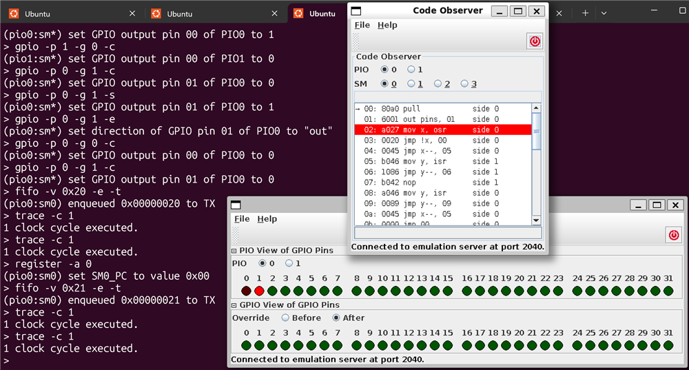
The emulator is a server. It runs your state machine designs. The server by default runs on port 2040 :). It can be controlled and queried via a set of client tools. The one that decides what happens, is the monitor client. With this one, you configure all aspects of the PIO state machine, program it, and make it run, step, get and set values.
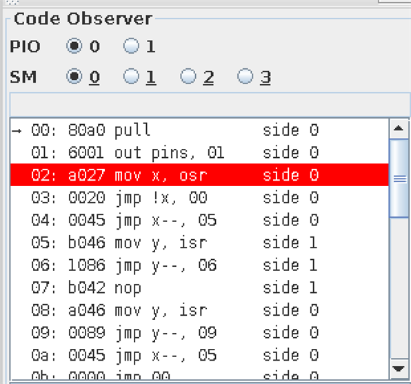
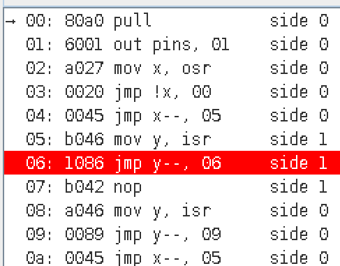
Then there is a set of graphical clients, that show specific aspects. The code observer shows what's loaded in the emulator, and where the program counter is:
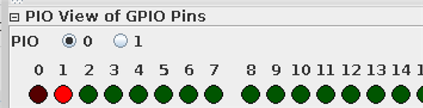
Also the interesting GPIO observer. That one shows how the state machine drives Pico GPIO pins. In the image below (and above too), the state machine has just read the direction bit for the stepper, and set GPIO1 to that value:
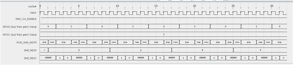
.. and a diagram client. Here showing my state machine, with the changes in X + Y scratch registers.
Here are example monitor commands that I used to entertain the emulator. If you know the architecture of the PIO controllers, this all makes sense:
; pin setup
pinctrl -p 0 -s 0 --out-count=2 --out-base=1
gpio -p 0 -g 0 -e
gpio -p 0 -g 1 -e
gpio -p 0 -g 0 -c
gpio -p 0 -g 1 -c
gpio --pio=0 --gpio=0 --init
gpio --pio=0 --gpio=1 --init
side-set -c 1
; shift LSBs
fifo --shift-right -t
; load program. the source has to be the hex values that the assembler generated
; you 'll typically find that back in the build/<mypiodesign>.pio.h file
load -f stepper_hex.pio
; enable state machine 0
sm +e
; set steps and dir in the TX fifo (will pull into OSR)
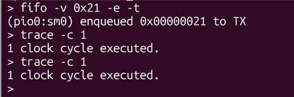
fifo -v 0x21 -e -t
; single step
trace -c 1
; get all register values
register
; move program counter to instruction 1 (0 based)
register -a 1
... and the hex representation of my PIO program, retrieved when building the code. This is what you load into the emulator.
You can also use https://wokwi.com/tools/pioasm to get the hex output of your design right away.
| pioasm output | emulator input | emulator code observer |
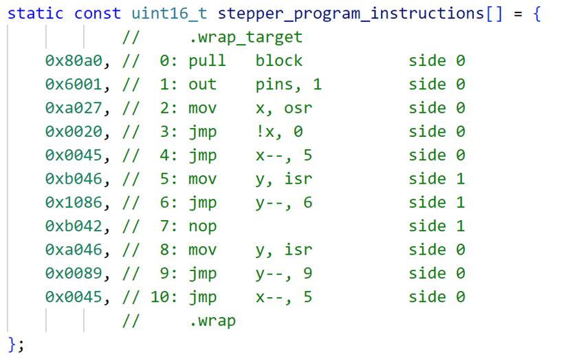 |
80a0 6001 a027 0020 0045 b046 1086 b042 a046 0089 0045 |
 |
Thank you for reading.
