element14 Community
element14 Community
    Register Log In
  • Site
  • Search
  • Log In Register
  • Community Hub
    Community Hub
    • What's New on element14
    • Feedback and Support
    • Benefits of Membership
    • Personal Blogs
    • Members Area
    • Achievement Levels
  • Learn
    Learn
    • Ask an Expert
    • eBooks
    • element14 presents
    • Learning Center
    • Tech Spotlight
    • STEM Academy
    • Webinars, Training and Events
    • Learning Groups
  • Technologies
    Technologies
    • 3D Printing
    • FPGA
    • Industrial Automation
    • Internet of Things
    • Power & Energy
    • Sensors
    • Technology Groups
  • Challenges & Projects
    Challenges & Projects
    • Design Challenges
    • element14 presents Projects
    • Project14
    • Arduino Projects
    • Raspberry Pi Projects
    • Project Groups
  • Products
    Products
    • Arduino
    • Avnet Boards Community
    • Dev Tools
    • Manufacturers
    • Multicomp Pro
    • Product Groups
    • Raspberry Pi
    • RoadTests & Reviews
  • About Us
  • Store
    Store
    • Visit Your Store
    • Choose another store...
      • Europe
      •  Austria (German)
      •  Belgium (Dutch, French)
      •  Bulgaria (Bulgarian)
      •  Czech Republic (Czech)
      •  Denmark (Danish)
      •  Estonia (Estonian)
      •  Finland (Finnish)
      •  France (French)
      •  Germany (German)
      •  Hungary (Hungarian)
      •  Ireland
      •  Israel
      •  Italy (Italian)
      •  Latvia (Latvian)
      •  
      •  Lithuania (Lithuanian)
      •  Netherlands (Dutch)
      •  Norway (Norwegian)
      •  Poland (Polish)
      •  Portugal (Portuguese)
      •  Romania (Romanian)
      •  Russia (Russian)
      •  Slovakia (Slovak)
      •  Slovenia (Slovenian)
      •  Spain (Spanish)
      •  Sweden (Swedish)
      •  Switzerland(German, French)
      •  Turkey (Turkish)
      •  United Kingdom
      • Asia Pacific
      •  Australia
      •  China
      •  Hong Kong
      •  India
      •  Korea (Korean)
      •  Malaysia
      •  New Zealand
      •  Philippines
      •  Singapore
      •  Taiwan
      •  Thailand (Thai)
      • Americas
      •  Brazil (Portuguese)
      •  Canada
      •  Mexico (Spanish)
      •  United States
      Can't find the country/region you're looking for? Visit our export site or find a local distributor.
  • Translate
  • Profile
  • Settings
Raspberry Pi
  • Products
  • More
Raspberry Pi
Blog Stepper Motor Control with Raspberry Pico PIO and DRV8711 driver- Part 6: autonomous PIO with speed control
  • Blog
  • Forum
  • Documents
  • Quiz
  • Events
  • Polls
  • Files
  • Members
  • Mentions
  • Sub-Groups
  • Tags
  • More
  • Cancel
  • New
Join Raspberry Pi to participate - click to join for free!
Featured Articles
Announcing Pi
Technical Specifications
Raspberry Pi FAQs
Win a Pi
GPIO Pinout
Raspberry Pi Wishlist
Comparison Chart
Quiz
  • Share
  • More
  • Cancel
Group Actions
  • Group RSS
  • More
  • Cancel
Engagement
  • Author Author: Jan Cumps
  • Date Created: 8 Apr 2025 8:09 PM Date Created
  • Views 1187 views
  • Likes 7 likes
  • Comments 7 comments
Related
Recommended
  • raspberry
  • pico
  • pico_eurocard
  • PIO
  • stepper-motor
  • c++

Stepper Motor Control with Raspberry Pico PIO and DRV8711 driver- Part 6: autonomous PIO with speed control

Jan Cumps
Jan Cumps
8 Apr 2025

The Pico has a set of PIO co-processors. They are real-time controllers that can execute logic with deterministic timing. Ideal to run strict-timed sequences and state machines. And to implement extra peripherals.
In this series, I'm trying to use the PIO to control a TI DRV8711 stepper motor controller.

image

Follow up of  Stepper Motor Control with Raspberry Pico PIO and DRV8711 driver- Part 5: a more autonomous PIO .

In the previous post, I wrote my own PIO program that can independently do up to 2147483647 steps. And the PIO handles the DIR pin.
In this post I add speed control.

PIO code

.program stepper
.side_set 1
.define public DELAY 0
.wrap_target
start:
    pull block                  side 0 ; Pull from FIFO to OSR
    out pins, 1                 side 0 ; shift direction out of OSR and output to dir
    mov x, osr                  side 0 ; Copy rest of OSR to scratch X
    jmp !x start                side 0
    jmp x-- tocks_h             side 0
tocks_h:
    mov y, isr                  side 1 ; ISR contains number of tocks to hold level
count_high:
    jmp y-- count_high          side 1 [DELAY] ; keep high for tocks
   ; removed because we don't need a symmetrical pulse for a stepper    
   ;  nop                         side 1 ; same size as low  
tocks_l:
    mov y, isr                  side 0 ; ISR contains number of tocks to hold level
count_low:
    jmp y-- count_low           side 0 [DELAY] ; keep high for tocks
    jmp x-- tocks_h             side 0 ; not done, keep loopins
.wrap

The code is somewhat extended since the version of the previous blog. I added an additional counter y, that holds the amount of ticks to stretch each half of the pulses.

It receives the value from the input shift register at the start of each half of the pulse, then keeps the step pin looping in that state until the y is 0.
Once that happens, it moves to the other half of the period, and does the same. Repeat until the pulse train is completed.

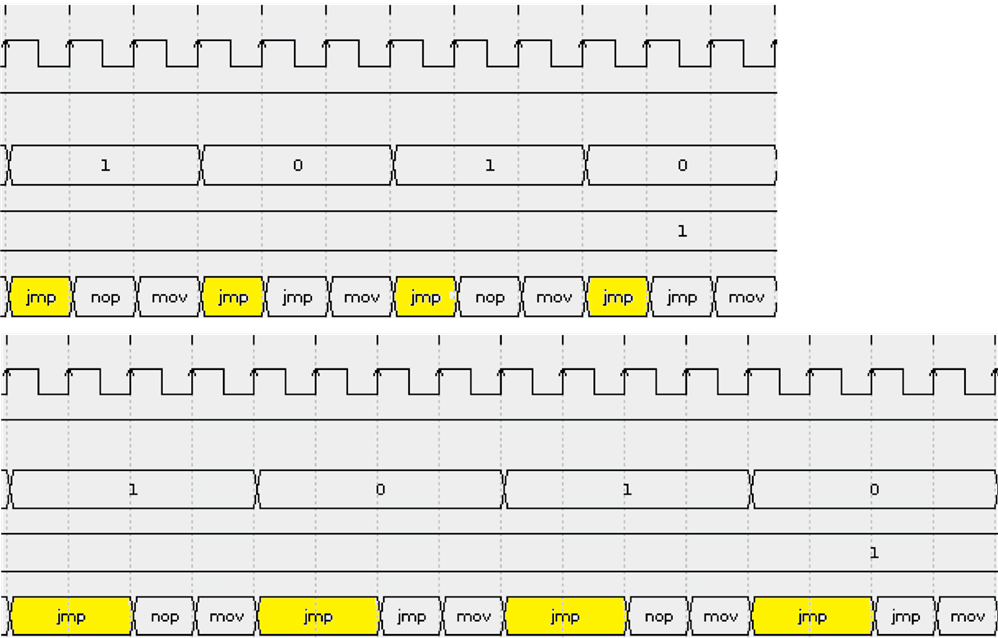
Here is how the pulse stretching works. The top trace is with no delay. Each half cycle takes 3 clock ticks. 6 clock ticks per full pulse period.
In the second trace, the delay was set to 1. The two half pulses now take an extra clock tick: 4 each, 8 ticks per full period. This effectively lowers the pulse train frequency, and thus slows the stepper motor down.

image

This is the tail of a command. The PIO has generated the amount of steps that were requested. X register has counted down to 0, and the flow stops, until a new command is sent by the ARM controller:

image

In later versions of this project I removed the nop instruction. It was there to have a nice symmetrical pulse train with 50% duty cycle.
But a stepper driver doesn't need that. It's removed, and that's one more code position that's available for other code in the same PIO.

In total, it now uses 11 lines (even if you use 4 motors on the same PIO). That leaves 21 instructions free for other designs.

The impact of removing this line is that a full pulse now takes 1 PIO clock tick less. But with typical delay settings in the mid to high 4000 range (and each delay eating 2 clock ticks), this is neglectable. In the end, we'll have 50.0xx% duty cycle instead of 50.00000%.

If you want exact 50%, you could add a delay of 1 to this line - making the amount of clock ticks for both halves of a pulse exactly the same:
mov y, isr side 1 [1]


If you want to learn how these graphs were generated:  emulate Raspberry PICO PIO programs .

You don't have permission to edit metadata of this video.
Edit media
x
image
Upload Preview
image

The main program

Here's the function that sets the speed:

void pio_pwm_set_delay(PIO pio, uint sm, uint32_t delay) {
    pio_sm_set_enabled(pio, sm, false);
    pio_sm_put_blocking(pio, sm, delay);
    pio_sm_exec(pio, sm, pio_encode_pull(false, false));
    pio_sm_exec(pio, sm, pio_encode_out(pio_isr, 32));
    pio_sm_set_enabled(pio, sm, true);
}

It stops the PIO, so don't use it (note to self) while the PIO is handling commands. 

in main(), I  just added a loop to slow down from requested speed in 4 steps

   std::array<command, 6> cmd{{
        {200 * microstep_multiplier, true}, 
        {200 * microstep_multiplier, false},
        {200 * microstep_multiplier, false},
        {400 * microstep_multiplier, false},
        {250 * microstep_multiplier, true},
        {350 * microstep_multiplier, true}}
    };

    uint32_t sleep_time = 0U;
    {

        wakeup_drv8711 w; // wake up the stepper driver
        sleep_ms(1); // see datasheet

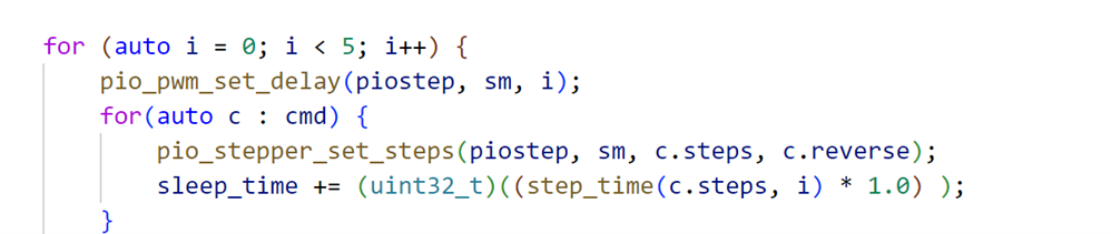
        for (auto i = 0; i < 5; i++) {
            pio_pwm_set_delay(piostep, sm, i);
            for(auto c : cmd) {
                pio_stepper_set_steps(piostep, sm, c.steps, c.reverse);
                sleep_time += step_time(c.steps, i); 
            }
            sleep_ms(sleep_time + 500); // give enough time to complete the action
        }
    }

The granularity is still rough. With these slow signals (850 Hz as fastest that my motor can handle in full-step mode), each delay adds 2 extra ticks. One tick is added to each half of the pulse. It's a lot. Making it more granular is something for a next exercise ...

Here is a full sequence, where I set the direction to 1, 2 steps, and a delay of 1. First 5 instructions are fetching the command, dir and delay. Then it's a loop, executed twice.

image

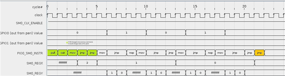
The last instruction wraps up after we're done, and lets the state machine fetch the next command.

GitHub drv8711 project repository.
GitHub PIO stepper lib repository.

Next:  Stepper Motor Control with Raspberry Pico PIO and DRV8711 driver- Part 7: autonomous PIO with interrupt when done 

Thank you for reading. I'll attach the project to the end of this post ...

  • Sign in to reply
  • DAB
    DAB 5 months ago

    Nice update Jan.

    You are making great progress.

    • Cancel
    • Vote Up 0 Vote Down
    • Sign in to reply
    • More
    • Cancel
  • Jan Cumps
    Jan Cumps 5 months ago

    I added an interrupt option. The PIO will raise an interrupt when it has completed the number of steps requested.

    It's optional, but useful if you want to do other activities when the motor has done some activities - and you don't ant to rely on calculations/estimations of time passed.

     Stepper Motor Control with Raspberry Pico PIO and DRV8711 driver- Part 7: autonomous PIO with interrupt when done 

    • Cancel
    • Vote Up 0 Vote Down
    • Sign in to reply
    • More
    • Cancel
  • Jan Cumps
    Jan Cumps 5 months ago in reply to Jan Cumps

    stepping through the code, and checking if scratch register X has the count of steps:

    image

    • Cancel
    • Vote Up 0 Vote Down
    • Sign in to reply
    • More
    • Cancel
  • Jan Cumps
    Jan Cumps 5 months ago

    It's not possible to debug a PIO, but there's a nice emulator: https://rp2040pio-docs.readthedocs.io/en/latest/index.html

    That one allows you to step and watch registers, FIFOs, and simulate in and out (either data or pins)

    Here, it's loaded with my stepper design, running on WSL ubuntu:

    image

    • Cancel
    • Vote Up 0 Vote Down
    • Sign in to reply
    • More
    • Cancel
  • Jan Cumps
    Jan Cumps 5 months ago in reply to ahsrabrifat

    you could call it assembler because every code instuction is exact one instruction of the controller. Less than 10 commands: https://rp2040pio-docs.readthedocs.io/en/latest/pio-programs.html#id2

    • Cancel
    • Vote Up 0 Vote Down
    • Sign in to reply
    • More
    • Cancel
>
element14 Community

element14 is the first online community specifically for engineers. Connect with your peers and get expert answers to your questions.

  • Members
  • Learn
  • Technologies
  • Challenges & Projects
  • Products
  • Store
  • About Us
  • Feedback & Support
  • FAQs
  • Terms of Use
  • Privacy Policy
  • Legal and Copyright Notices
  • Sitemap
  • Cookies

An Avnet Company © 2025 Premier Farnell Limited. All Rights Reserved.

Premier Farnell Ltd, registered in England and Wales (no 00876412), registered office: Farnell House, Forge Lane, Leeds LS12 2NE.

ICP 备案号 10220084.

Follow element14

  • X
  • Facebook
  • linkedin
  • YouTube