element14 Community
element14 Community
    Register Log In
  • Site
  • Search
  • Log In Register
  • About Us
  • Community Hub
    Community Hub
    • What's New on element14
    • Feedback and Support
    • Benefits of Membership
    • Personal Blogs
    • Members Area
    • Achievement Levels
  • Learn
    Learn
    • Ask an Expert
    • eBooks
    • element14 presents
    • Learning Center
    • Tech Spotlight
    • STEM Academy
    • Webinars, Training and Events
    • Learning Groups
  • Technologies
    Technologies
    • 3D Printing
    • FPGA
    • Industrial Automation
    • Internet of Things
    • Power & Energy
    • Sensors
    • Technology Groups
  • Challenges & Projects
    Challenges & Projects
    • Design Challenges
    • element14 presents Projects
    • Project14
    • Arduino Projects
    • Raspberry Pi Projects
    • Project Groups
  • Products
    Products
    • Arduino
    • Avnet Boards Community
    • Dev Tools
    • Manufacturers
    • Multicomp Pro
    • Product Groups
    • Raspberry Pi
    • RoadTests & Reviews
  • Store
    Store
    • Visit Your Store
    • Choose another store...
      • Europe
      •  Austria (German)
      •  Belgium (Dutch, French)
      •  Bulgaria (Bulgarian)
      •  Czech Republic (Czech)
      •  Denmark (Danish)
      •  Estonia (Estonian)
      •  Finland (Finnish)
      •  France (French)
      •  Germany (German)
      •  Hungary (Hungarian)
      •  Ireland
      •  Israel
      •  Italy (Italian)
      •  Latvia (Latvian)
      •  
      •  Lithuania (Lithuanian)
      •  Netherlands (Dutch)
      •  Norway (Norwegian)
      •  Poland (Polish)
      •  Portugal (Portuguese)
      •  Romania (Romanian)
      •  Russia (Russian)
      •  Slovakia (Slovak)
      •  Slovenia (Slovenian)
      •  Spain (Spanish)
      •  Sweden (Swedish)
      •  Switzerland(German, French)
      •  Turkey (Turkish)
      •  United Kingdom
      • Asia Pacific
      •  Australia
      •  China
      •  Hong Kong
      •  India
      •  Korea (Korean)
      •  Malaysia
      •  New Zealand
      •  Philippines
      •  Singapore
      •  Taiwan
      •  Thailand (Thai)
      • Americas
      •  Brazil (Portuguese)
      •  Canada
      •  Mexico (Spanish)
      •  United States
      Can't find the country/region you're looking for? Visit our export site or find a local distributor.
  • Translate
  • Profile
  • Settings
Raspberry Pi
  • Products
  • More
Raspberry Pi
Blog Experimenting with a Raspberry Pi GPIO Pin
  • Blog
  • Forum
  • Documents
  • Quiz
  • Events
  • Polls
  • Files
  • Members
  • Mentions
  • Sub-Groups
  • Tags
  • More
  • Cancel
  • New
Join Raspberry Pi to participate - click to join for free!
Featured Articles
Announcing Pi
Technical Specifications
Raspberry Pi FAQs
Win a Pi
GPIO Pinout
Raspberry Pi Wishlist
Comparison Chart
Quiz
  • Share
  • More
  • Cancel
Group Actions
  • Group RSS
  • More
  • Cancel
Engagement
  • Author Author: jc2048
  • Date Created: 15 Mar 2020 5:43 PM Date Created
  • Views 2812 views
  • Likes 7 likes
  • Comments 10 comments
Related
Recommended
  • python
  • gpio
  • experimenting
  • pi 3 b+
  • pi day

Experimenting with a Raspberry Pi GPIO Pin

jc2048
jc2048
15 Mar 2020

It's Pi Day [well, almost: news travels slowly where I am] and I thought I'd add a simple electronic experiment to all the other good stuff that people are doing.


Not all experimenting has to be complicated or requires the use of lots of expensive equipment. I was curious about the GPIO pins on a Pi 3 Model B+, the one that I bought to attempt the PiCasso Design Challenge last year, so I thought I'd have a quick go at measuring one of the basic characteristics myself rather than simply looking up the figures. They are probably going to be very similar to any microcontroller, but I'd like to see for myself.


The method is going to be very simple. I'm going to load the output with a resistor to the opposite rail to the one the output is pulling to, measure the current through the resistor and the voltage difference between the rail and the output, and plot the results on a graph for both a logic high and a logic low output. To set the output, I'll use a simple piece of Python code.


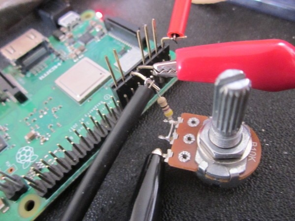
Here's what it looks like. I made the resistor a 10k potentiometer in series with a 47R. Unfortunately it's a linear pot, so at higher currents it is very touchy to adjust. The 47R is to limit the current to no more than 70mA, which I reckoned the Pi would survive for the time it would take me to notice and reduce it.


image


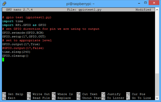
Here's the Python code I used. It's sitting in the Nano editor on the Pi, as viewed remotely via Putty. It just sets the output of GPIO17 either high or low and waits for 4 minutes before ending. I could have done more with it but there wasn't any point.


image


The voltage and current were each measured with a handheld multimeter.


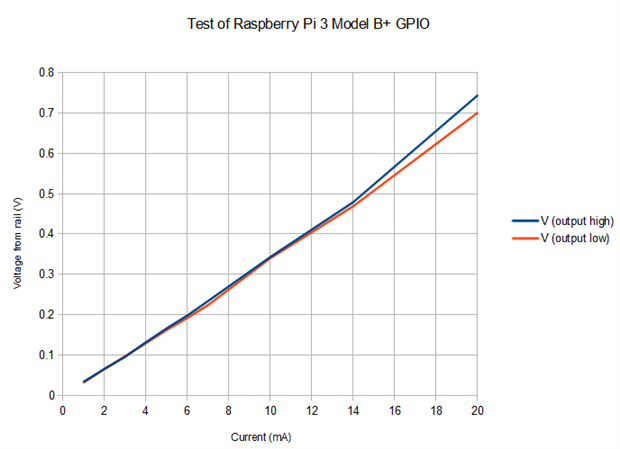
Here's the graph I got.


image


The voltage is the difference from the respective rail, so is approximately the voltage dropped by the internal MOSFET. Keep in mind that, as an experiment, this is very 'rough and ready'. The slope of the line [voltage over current] is a resistance, roughly speaking the rds(on) of the MOSFET. At lower currents, that's looking like about 30 Ohms. It goes off a bit at higher currents [how real that is is perhaps open to question - it was getting hard to adjust the current accurately by that stage - but we might also surmise that local heating of what is a fairly small transistor is changing the rds(on) value].


Happy Pi Day everyone.


If you found this interesting and would like to see more blogs I've written, a list can be found here: jc2048 Blog Index

  • Sign in to reply

Top Comments

  • dougw
    dougw over 5 years ago +3
    I'm impressed that it could source and sink 20 mA. That is good to know.
  • DAB
    DAB over 5 years ago +2
    Good test. When I ran some tests on the RPi output I found they tend to float, so sometimes you do not get clean transitions unless you use external termination resistors. DAB
  • jc2048
    jc2048 over 5 years ago in reply to dougw +2
    But note that I'm not showing what current it's safe to take from an output. You'd need to look at the manufacturer's data for that. My 20mA just seemed like a reasonable figure to work up to for the test…
  • jc2048
    jc2048 over 5 years ago in reply to dougw

    But note that I'm not showing what current it's safe to take from an output. You'd need to look at the manufacturer's data for that. My 20mA just seemed like a reasonable figure to work up to for the test.

    • Cancel
    • Vote Up +2 Vote Down
    • Sign in to reply
    • More
    • Cancel
  • dougw
    dougw over 5 years ago

    I'm impressed that it could source and sink 20 mA. That is good to know.

    • Cancel
    • Vote Up +3 Vote Down
    • Sign in to reply
    • More
    • Cancel
  • clem57
    clem57 over 5 years ago in reply to jc2048

    Because of Pi day, you got the Raspberries.image

    • Cancel
    • Vote Up +1 Vote Down
    • Sign in to reply
    • More
    • Cancel
  • jc2048
    jc2048 over 5 years ago in reply to genebren

    And I got 50 points for what must be the simplest blog I've done for a long time.


    I think, maybe, the system has gone wrong, because I seem to be getting 50 points every time I subsequently comment here. [As I now have three raspberries, does that mean I get the jackpot as well?]

    • Cancel
    • Vote Up +1 Vote Down
    • Sign in to reply
    • More
    • Cancel
  • jc2048
    jc2048 over 5 years ago in reply to clem57

    Actually, there is an LED in the background of the picture (the power light), but it doesn't form part of the experiment. In case it wasn't very clear to anyone (I might have done it better if I had put in a bit more explanation), the experiment is measuring each of the internal pair of complementary MOSFETs that make up the pin driver, inside the processor, to see how they behave. Not too surprisingly, they behave like MOSFETs do.


    Knowing the rds(on) might be useful if you wanted to drive a series-terminated length of microline on a board. If the line were 50R, you'd need to add about 18R or 22R to pad the MOSFET figure to the 50R.


    Other than that, just keep in mind that the output voltage will move away from the rail as you take more current from it.

    • Cancel
    • Vote Up +1 Vote Down
    • Sign in to reply
    • More
    • Cancel
>
element14 Community

element14 is the first online community specifically for engineers. Connect with your peers and get expert answers to your questions.

  • Members
  • Learn
  • Technologies
  • Challenges & Projects
  • Products
  • Store
  • About Us
  • Feedback & Support
  • FAQs
  • Terms of Use
  • Privacy Policy
  • Legal and Copyright Notices
  • Sitemap
  • Cookies

An Avnet Company © 2025 Premier Farnell Limited. All Rights Reserved.

Premier Farnell Ltd, registered in England and Wales (no 00876412), registered office: Farnell House, Forge Lane, Leeds LS12 2NE.

ICP 备案号 10220084.

Follow element14

  • X
  • Facebook
  • linkedin
  • YouTube