


This week we have been putting together some Gertboard & Raspberry Pi demo kits for Design West. The idea is that you can control a linear actuator and a few other pieces of hardware using the Gertboard. Gert Van Loo will be giving the demo next week at the Design West Exhibition, so if you're there, drop by and check out our handiwork! Here's the story of our build.
The decision to laser cut the Gertboard Experimenter Kits came quickly. We needed to create an enclosure that would support a Raspberry Pi, Gertboard, 10k potentiometer, linear actuator and battery. It had to look good, and it had to be ready within a week.
The brief was simple. Deceptively so. Deliver 15+ kits to the United States to be used at Design West, San Jose. 15 kits didn’t seem like much, a day’s work perhaps. How hard could it be? With that in mind, I set out on Adobe Illustrator at 3 pm on Friday afternoon. It is the closest thing I have to a CAD program, other than CadSoft EAGLE and I knew that whatever I had to design had to be exact. We grabbed a pen and sketched out the very rough idea of what the shape of the kit might be. It definitely had a “Victorian school desk” feel to it, but it seemed to fit quite nicely with the idea of it being an education kit. Given the time constraints, it had to be simple to assemble and using the laser cutter at the Leeds Hackerspace seemed like a great solution.
A couple of weeks prior to the build Paul had sorted out the components, most of which we could get out of our warehouse, but some of which we had to source from other places. We didn’t have all the parts in the office on Friday afternoon so I had to do some serious spec sheet cribbing to get the dimensions of components like the slide pot.

A few of the parts would require modification, especially the linear actuator, which would need a geared 12 V motor attaching in place of the 9 V motor. The 9 V motor which came attached to the rest of the actuator was too quick since it needed to be driven directly from the 9 V battery. Gert wasn’t too keen on using a PWM solution to slow the motor down as the demo was supposed to be as simple as possible for teaching purposes. The slower geared motor made coding the actuator movement much easier. This meant that the CAD drawing would have to be set out not fully knowing the dimensions of the modified linear actuator. Gert put a diagram together showing how the new motor would fit the actuator and dimensioned it so I could add it to the drawing.
I usually use Illustrator for illustrations and diagrams, so I didn’t know (and still don’t know) whether you can add relationships between objects in the way that you can on programs like Solidworks or Pro Desktop. Each time I wanted to add a marking or hole at a given distance from another object, I had to draw a rectangle to use as a ruler. This was laborious, but seemed to work out. At least on paper. At about 7 pm I had most of the design but took my laptop back and tweaked it in the evening. Working with a touch pad on a laptop in Illustrator was another challenge.
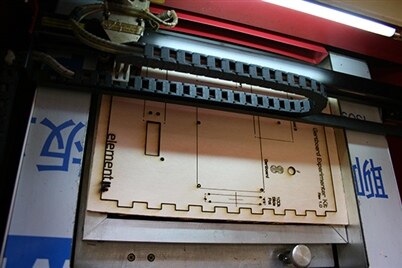
Nonetheless, by 1 pm the next day I had the drawing ready to go. Then I looked up the laser cutter. Ah, a problem. I’d given the components lots of space so that the kit would be easy to put together. The LS3020 from HPC Laser Ltd turned out to have a roughly A4 cutting area. A hasty resizing took place to fit the design into this space.

Next, we would need to get hold of the wood. I figured that plywood would be a good medium. We chose it over acrylic for the way it looks when it is burned by the laser and because it was more readily available. The only acceptable thickness I could track down at 3 pm on Sunday afternoon that would fit in my car was 6 mm. Seemed a bit thick for a laser cutter, but hey, I’d seen that it could cut up to 8 mm so I invested. I’d never been to a hackerspace before Sunday, so it was interesting to finally see the one in Leeds. Angus and my brother Bob sacrificed their Sunday afternoons to set up the laser cutter and after a couple of test cuts is sliced with buttery ease through the ply. Success! By the evening we had a prototype. Most of the holes seemed to be in the right place. However, it had taken nearly 4 hours to get the first box cut, so the design would have to be modified. The cutting was pretty quick, but the etching of text and logos took an age.

The next day, I arrived bright and early to the element14 office in Leeds. Paul and I decided it was important to take the prototype way on down south to Cambridgeshire so that we could put the kit together with Gert. We headed to our trade counter and picked up a massive box of all the parts we would need for the 15 kits. At this point we still hadn’t tried to fit the parts into the mounting so by the time we were down south in the late afternoon, it was a relief that mostly everything slotted right into place. Only a few holes would need changing. Some would be swapped to pilot holes, some removed entirely.
There were bigger tasks than merely slotting one prototype together. The hacking of the linear actuator that I alluded to earlier had to be thought through pretty carefully. Although disassembling the actuators was easy and angle grinding the motors from the shafts fairly quick, extra holes still had to be drilled and reassembly pondered. For this, jigs had to be constructed and 40 nylon stand-off spacers drilled smooth.
Finding a way to reattach the more powerful motors directly to a shaft when both of the ends were shear was really tricky. Nick, a friend and colleague of Gert, had very kindly volunteered to help and let us borrow his workshop for the evening. Being particularly mechanically minded (as well as being a Broadcom chip designer), Nick suggested using a sleeve of PVC tubing to sheath the motor and shaft. Luckily, he had some to hand which was the right size for an interference fit with the screw shaft. A drop of superglue sealed the union. You can see from the picture that the shaft looks a little "eccentric", but the connection is flexible enough to allow the assembly to straighten out once it's screwed into place.
One of the other difficult tasks was to find a way to position the two sets of microswitches so that the linear actuator could trigger the “programming” switch before depressing a cut-off safety switch at either end. The programming switches had a longer throw and in the end we used these to press the safety cut-off in turn. This meant that they had to be carefully positioned relative to the exact position of the actuator.
Some time later after much cutting, drilling and reassembly, we had the tricky elements finished. The test programs were a success and we had a working prototype. Back on the road to Leeds. At this point, it was starting to seem like 15 was a very big number.

There was only one thing for it. We would need to optimise our production process. The next evening in the Hackerspace we aimed to produce all of the boards we would need. Disaster struck. For some reason, the laser wasn’t cutting through the 6 mm ply. The lens seemed clean, the alignment wasn’t too bad. We upped the power. More smoke, more flames, but still the cut didn’t reach all the way through. We slowed the cutting speed right down. Again, the same result. Each successive cut was more and more difficult to “persuade” out of its frame. By 1:30 am we had about 10 front plates cut. They had no labelling. They were splintering at the back. The blackened areas were becoming more and more pronounced. All the guys from Leeds Hackerspace tried to help. They were massively generous with their time, but still we couldn’t figure out what was wrong. Was it the wood? Was it the cutter? In the end, we decided to try and spray paint the front labels for the board to avoid the long time that it took to etch, which could have looked cool, but turned out ...not very well. The paint bled under the stencil so we needed to find a better, faster solution! There was an off-chance, said one of the guys, that we could call a business in Keighley called Fab Lab and ask to use their bigger laser cutter.
The next morning, I got on the phone to Fab Lab and asked them whether they could help us with our cutting problem. They were amazing and agreed to let us use their machine from 1 pm that day. We got hold of some 3.6 mm plywood from Woodworks Timber Ltd to err on the side of caution. They were super quick at turning around 40 sheets, cut to size. It wasn’t a big order, but they really helped us out. Another swift redesign was in order to shorten the “turrets” from 6 to 3.6 mm. Whilst Vicky and Pat (who work on the element14 website) did the final assembly on the actuators, Paul and I headed off to Keighley. It should be mentioned here that Stu and Iro (our social media and marketing friends) helped to screw all the Raspberry Pis and Gertboards to the mounting plates. Unfortunately, we had to reverse their hard work later on!
We didn’t know what to expect from Fab Lab and I was starting wonder whether we would be able to build the kits on time. In spite of the sleep deprivation and few costly wrong moves, the decision to call Fab Lab was a very good one. Dave, of Fab Lab, helped us to cut an initial prototype (v1.1). Everything fitted together. It looked great. A couple of tweaks to cut the text at low power rather than etch each word. Now we were cooking on gas.

In three hours we had turned out 16 perfectly cut sets which just needed assembly. The thinner ply was a little more prone to bowing, but it didn’t seem to make much difference in the cutter.
At this point, it’s worth mentioning that Fab Lab had amazing equipment and facilities, ranging from 3D printers and small milling machines up to a large CNC machine. Their staff were very helpful and I’m ashamed to say I’d not known about them before. They open up their facilities to the community and are very helpful to local individuals or businesses wanting rapid prototyping.


The next morning we could start the final build. A whole team of volunteers pitched in and we set up a makeshift production line in the room that we usually use for shooting product demo videos. We divided up the tasks between a team of about 8, including all of our friends and colleagues mentioned above, as well as Dave, Gemma and Aga (from our creative and marketing teams). It was a huge team effort to replicate the prototype wiring on a further 16 kits. With Adam Smith inspired division of labour, we were soon able to get the kits together. Soldering skills were learned. Tape was removed. Rows of kits started to look complete.


By about 4:30 pm on Thursday, we had the kits finished. Much use of the hot glue gun, several soldering irons and a frenzy of connecting jumpers and straps was the final hurdle, but eventually we got 16 identical kits together and packaged up with the help of our postie, Jez. Now the kits are winging their way to Design West time for Gert to give the demo! Fingers crossed they make it there safely.
We will post the wiring diagram and some other bits and pieces, including the .ai and .dxf files for the base box after the exhibition.

