



element14 Community
element14 Community
    Register Log In
  • Site
  • Search
  • Log In Register
  • Community Hub
    Community Hub
    • What's New on element14
    • Feedback and Support
    • Benefits of Membership
    • Personal Blogs
    • Members Area
    • Achievement Levels
  • Learn
    Learn
    • Ask an Expert
    • eBooks
    • element14 presents
    • Learning Center
    • Tech Spotlight
    • STEM Academy
    • Webinars, Training and Events
    • Learning Groups
  • Technologies
    Technologies
    • 3D Printing
    • FPGA
    • Industrial Automation
    • Internet of Things
    • Power & Energy
    • Sensors
    • Technology Groups
  • Challenges & Projects
    Challenges & Projects
    • Design Challenges
    • element14 presents Projects
    • Project14
    • Arduino Projects
    • Raspberry Pi Projects
    • Project Groups
  • Products
    Products
    • Arduino
    • Avnet & Tria Boards Community
    • Dev Tools
    • Manufacturers
    • Multicomp Pro
    • Product Groups
    • Raspberry Pi
    • RoadTests & Reviews
  • About Us
    About the element14 Community
  • Store
    Store
    • Visit Your Store
    • Choose another store...
      • Europe
      •  Austria (German)
      •  Belgium (Dutch, French)
      •  Bulgaria (Bulgarian)
      •  Czech Republic (Czech)
      •  Denmark (Danish)
      •  Estonia (Estonian)
      •  Finland (Finnish)
      •  France (French)
      •  Germany (German)
      •  Hungary (Hungarian)
      •  Ireland
      •  Israel
      •  Italy (Italian)
      •  Latvia (Latvian)
      •  
      •  Lithuania (Lithuanian)
      •  Netherlands (Dutch)
      •  Norway (Norwegian)
      •  Poland (Polish)
      •  Portugal (Portuguese)
      •  Romania (Romanian)
      •  Russia (Russian)
      •  Slovakia (Slovak)
      •  Slovenia (Slovenian)
      •  Spain (Spanish)
      •  Sweden (Swedish)
      •  Switzerland(German, French)
      •  Turkey (Turkish)
      •  United Kingdom
      • Asia Pacific
      •  Australia
      •  China
      •  Hong Kong
      •  India
      •  Japan
      •  Korea (Korean)
      •  Malaysia
      •  New Zealand
      •  Philippines
      •  Singapore
      •  Taiwan
      •  Thailand (Thai)
      •  Vietnam
      • Americas
      •  Brazil (Portuguese)
      •  Canada
      •  Mexico (Spanish)
      •  United States
      Can't find the country/region you're looking for? Visit our export site or find a local distributor.
  • Translate
  • Profile
  • Settings
Raspberry Pi
  • Products
  • More
Raspberry Pi
Blog Google's Alexa-like Pi AIY Kit, mini teardown
  • Blog
  • Forum
  • Documents
  • Quiz
  • Events
  • Polls
  • Files
  • Members
  • Mentions
  • Sub-Groups
  • Tags
  • More
  • Cancel
  • New
Join Raspberry Pi to participate - click to join for free!
Featured Articles
Announcing Pi
Technical Specifications
Raspberry Pi FAQs
Win a Pi
GPIO Pinout
Raspberry Pi Wishlist
Comparison Chart
Quiz
  • Share
  • More
  • Cancel
Group Actions
  • Group RSS
  • More
  • Cancel
Engagement
  • Author Author: shabaz
  • Date Created: 4 May 2017 6:30 PM Date Created
  • Views 13028 views
  • Likes 20 likes
  • Comments 66 comments
Related
Recommended
  • aiy google
  • google aiy
  • google sdk
  • google_aiy
  • aiy
  • raspberry_pi
  • raspberry pi
  • amazon alexa
  • aiyproject
  • raspberry pi 3
  • aiy project
  • google embedded sdk
  • raspberry_pi_3

Google's Alexa-like Pi AIY Kit, mini teardown

shabaz
shabaz
4 May 2017

Google has been busy getting stuff attached to MagPi magazines.. I spotted a box containing an 'AIY' kit at the local magazine retailer. Basically it is a card box with some electrical parts and the MagPi magazine.

It is like a cut-down DIY version of Amazon Alexa from what I can tell.


They had plenty at closing time, so I suspect there will be lots for people to buy tomorrow too, but from examination it is an audio card and a few peripherals. USB sound cards are cheap these days so that is another option for those who don't/can't purchase the magazine.

Below are photos of the contents of the box (just the electronic bits are shown, there is also a cardboard self-assembly enclosure and the MagPi magazine itself; I might take photos of that later), like a mini-teardown where the teardown is already done.


I think it's fair to say the kit component-wise is a little boring, but at least it's cheap. The stereo mic is good to see though. And maybe more projects will be available in future.

Also there are other ways to achieve Alexa-like capability (from both a hardware and PaaS vendor perspective).

For higher quality there are multi-microphone options for Pi, although of course they are more expensive.


Where the fun will come in is with the software - it will be a lot of fun to create voice-enabled projects.

Although it is intended to use Google PaaS, not everyone likes sending audio to a cloud, but it is usable for standalone non-Internet-connected audio projects too, e.g. music player. No need to plug in the microphone wires.


In summary, it is nice to see traction with voice-enabled natural language assistant projects for hobbyists, and the hardware here is very basic, but at least it keeps interest up and lots of opportunities for those learning programming to have fun and create some cool projects.


Some photos and notes follow, as well as any reverse-engineered schematics. Also see the comments section.


image


Connections Overview

According to google's page, these are the connections (see diagram below). Handily the Pi's I2C, SPI and UART connections are broken out to pads all ready for soldering to the supplied SIL header pins.

There are also some output pins, probably MOSFET driven (can see what looks like SOT-23 sized MOSFETs marked G31 D5 (they are most likely N-channel MOSFETS part code Diodes Inc DMG3420U) on the right of the image along with SMD fuse and diode per output).

See further below for reverse-engineered schematic for that.


On the left of the board, there is space for soldering SIL pins for attaching hobby servo motors.
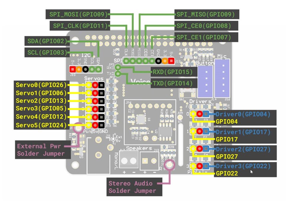
image

Output Drivers

The four drivers (shown on the right side of the diagram above) have most likely the following circuit - I think it is accurate but please let me know in the comments if it isn't:
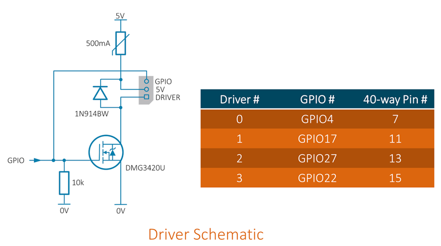
image

The four MOSFETs are used in an open drain configuration, so the pins marked 'DRIVER' will be switched to ground (0V) whenever the corresponding GPIO pin goes high. If the desired load is 5V powered then the 5V pin can be used to provide power (there is a 500mA resettable fuse). The open drain configuration also allows a lower voltage source to be used to supply the load, and the MOSFET will switch the other end of the load to ground.

The diagram below shows how to connect a relay with a 5V coil. It is inadvisable to use the Driver outputs with a higher voltage despite it being an open drain configuration because current can flow through the diode in the schematic above and the fuse, causing damage.

Also, it is strongly advised not to use this for connecting mains operated equipment, because there are regulations governing what enclosure is used and how the cable is secured and so on. To control mains equipment it is good to use home automation methods such as wireless (there are radio transmitters available for the Pi).
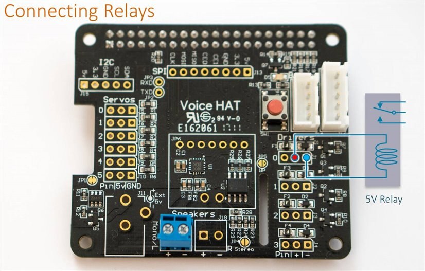
image


A suitable relay could be Finder 5V coil SPDT 6A contacts changeover relayFinder 5V coil SPDT 6A contacts changeover relay or Finder SPST 6A relaySPST 6A relay . Both of these relays are very compact (20x10x10mm) and have pins that will fit a breadboard or stripboard so are easy to prototype with. The comments section further below has a photo of how to wire it up and some example Python code to test it by turning the relay on and off. Although these relays can be used with mains, it would be extremely inadvisable to do so without a decent PCB layout (not stripboard!) and other precautions (see here for some reasons). So, the relay control is best used for lower-voltage tasks.


Mains Control

One solution is to use wireless control. This can be country or region specific.

UK

I've used an Energenie wireless module before, it is a very small transmitter board that connects to the Pi and wirelessly controls mains sockets. The Energenie kitEnergenie kit comes with the wireless transmitter board and two sockets. It's good value, and meets the relevant electrical standards for the UK. It could be wired to the connections on the left side of the google voice HAT board allocated for Servos for example (by default it needs six GPIO although that number can optionally be reduced if needed).


Audio Output

The centre of the board contains the integrated circuit (IC) with the audio digital-to-analog converter and mono audio amplifier inside it, it is Maxim MAX98357A - thanks Inderpreet! (the 16-pin QFN sized IC says AKK BDK on it) and an EEPROM marked 24C32F.


image

Power Connections

There is also space for a DC power jack but none is fitted. A DC power jack with thin pins would fit. There is a SOT23-6 part near it, marked K4S DD and a SOT-23 part marked 23X D1 is close too. These two parts have a Q identifier, so are likely some type of transistors.


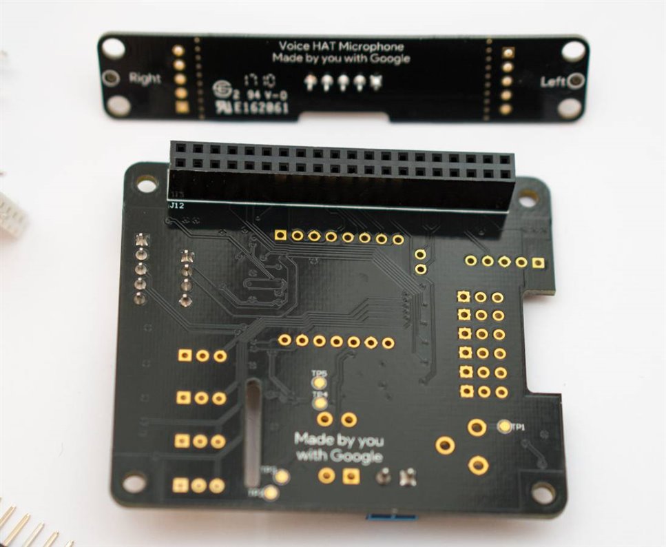
Microphone Board

The microphones are marked 432 QDF21G and are Knowles SPH0645LM4H (thanks again Inderpreet) MEMS digital microphones. They directly output an I2S bitstream.
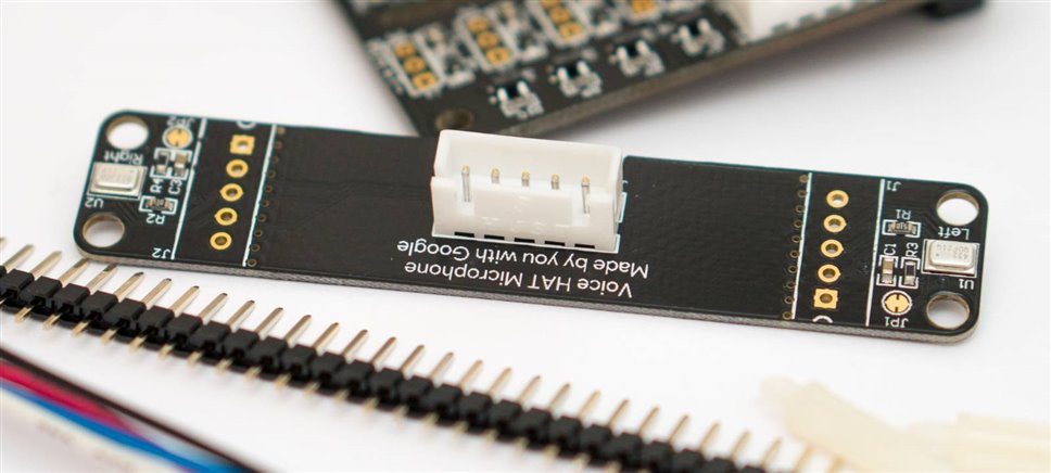
image


The microphone input ports are on the underside:
image


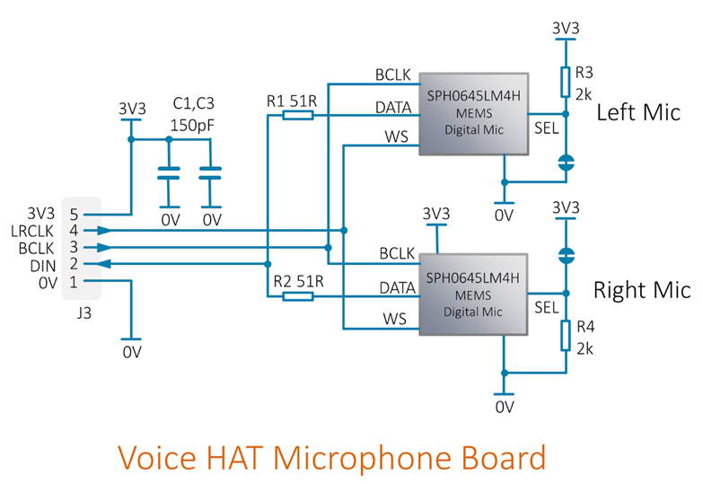
This is the schematic of the microphone board, using the information from Inderpreet in the comments below. There may be some minor mistakes (please let me know in the comments section and I'll correct it). In theory the microphone board could be used standalone with the Pi, no need for the main Voice HAT board. It is a convenient breakout board for the surface-mount mics.


It could be suitable for small projects, e.g. with the 'Zero or with other boards with an I2S interface. It would be advisable to have a small resistance (e.g. 51 ohms) in series with the LRCLK and BCLK pins if it is connected directly.

There is nothing to stop a voice assistant from working without a speaker (you just won't hear the result, unless the on-board headphone socket on the Pi 3 is used perhaps).

Not all projects would require an audio response. Also, for some projects one may prefer a discreet response in an earphone (e.g. check your calendar by requesting it, but not announcing your plans to everyone).
image


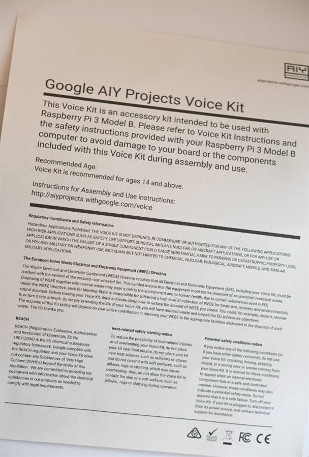
Safety Leaflet

This is enclosed in the box:
image

  • Sign in to reply

Top Comments

  • nicklansley
    nicklansley over 9 years ago +5
    I managed to get hold of a copy of MagPi magazine and get it working with a Raspberry Pi 3: www.youtube.com/watch
  • ipv1
    ipv1 over 9 years ago +4
    I have a suspicion that that is not a code but rather an I2S amplifier - MAX98357A I just googled it and sure enough... I have one of those in stock from an unfinished project and just recalled it as I…
  • ipv1
    ipv1 over 9 years ago in reply to shabaz +4
    If I remember correctly, shabaz sir, you did a stereo i2s sound card circuit for the BBB some time back. Theoretically, that can be used here as well. I think I need to read more about that
  • shabaz
    shabaz over 9 years ago in reply to jhewitt123

    Hi John,


    That's correct, if the relay module has three pins, they won't directly map to the three grouped pins on the HAT board.

    The HAT board markings are a bit misleading, they say Pin|+|- but the '-' doesn't mean ground. So, if you want to use the relay module board, then the three wires from that module won't connect to the three grouped pins. Instead, the ground pin on the module would need to be wired to a pin marked GND on the HAT board (there are some pins elsewhere on the HAT board which are marked GND). Furthermore, the signal connection would need some additional consideration. It would most likely need a resistor connected from the signal pin to +5V, so that the pin can 'float' up. The grouped pin marked '-' would then pull the signal pin low. This is a very non-ideal situation though, because it would mean that by default the relays are energized. This could have other implications for the rest of the project.

    For these reasons, it is best to use a relay on its own. The ebay modules are providing no benefit in this situation, because the HAT board can power a relay anyway, and there is already isolation inherent in the relay. If you did want to use the ebay module, then another idea is to desolder the relay and use it on its own, or, maybe easier, cut some tracks so that you can bypass the circuitry on the ebay module so that the coil on the relay is directly energized by the HAT board.

    • Cancel
    • Vote Up +1 Vote Down
    • Sign in to reply
    • More
    • Cancel
  • jhewitt123
    jhewitt123 over 9 years ago in reply to shabaz

    Yes, while that would work, what I am saying is your schematic that shows

    the - drive of the MosFETs at ground is not what I am measuring on my

    powered board. I see 17K ohms to the servo ground pin, and 42K ohms between

    channels of the FET drives. I'd say for most part, in the real world now adays for relay apps people get the

    cheap china relay modules with built in LEDs and/or the opto isolated

    versions which also have three pins on the control side, including the

    power pins unless one knows how to wire them to power and ground and the proper link to the MOSFET pins, which is still in the ether somewhere.. These won't work with the HAT that does not have a real ground

    on the drive or am I missing something.


    In other words, if the drive pins were really ground I would imagine they would say gnd like the servo pins do, not - . Same sentiments apply for the power pins.

    • Cancel
    • Vote Up +1 Vote Down
    • Sign in to reply
    • More
    • Cancel
  • shabaz
    shabaz over 9 years ago in reply to jhewitt123

    Here is one way to do it, if I was using just a relay on its own. I used a SPDT Finder RelaySPDT Finder Relay, which is good for up to 6A load. It has pin spacings which make it fit normal stripboard.

    (This layout isn't for mains, just for low-voltage, because the stripboard layout doesn't have the necessary clearances, nor does it meet any other standards).

    image

    image


    It is wired to the HAT board like this:

    image

    When I run a test program, I can hear it click away, so it is functioning. This was the program, saved to a file called relay-test.py:

    # Connect relay to GPIO4 (pin 7)  
    import time  
    import RPi.GPIO as GPIO  
    GPIO.setmode(GPIO.BCM)  
    GPIO.setup(4, GPIO.OUT)  
    for x in range (0, 2):
      GPIO.output(4, True)  
      time.sleep(1)
      GPIO.output(4, False)
      time.sleep(1)
    time.sleep(3)  
    GPIO.cleanup()


    To run it, I used:


    sudo python relay-test.py

    • Cancel
    • Vote Up +3 Vote Down
    • Sign in to reply
    • More
    • Cancel
  • shabaz
    shabaz over 9 years ago in reply to jhewitt123

    Hi John,


    Do you have a link to the module you're using? I think it can be used but the topology will be slightly different to the relay-only circuit.

    I suspect the 5V and 0V connections will have to be wired to 5V and GND (i.e. 0V) on the board (the '-' is not the GND connection but a switched connection due to the open drain design, so it is slightly misleading print on the board) and then the signal pin could be dealt with in a couple of ways but I wanted to check any info you have regarding the module you're using.

    If the board you have has a 5V relay on it, then another easier way is to just bypass any circuitry on the board and use the relay only, since there is no need for optoisolation with the relay, the output is isolated already inside the relay.

    • Cancel
    • Vote Up 0 Vote Down
    • Sign in to reply
    • More
    • Cancel
  • jhewitt123
    jhewitt123 over 9 years ago in reply to shabaz

    Shabaz, the issue I was having with the MosFET DMG3420U driver schematic is in trying to drive a common 5V opto-isolated relay module.Instead of two pins, it has ground, power and signal. It doesn't show the power on LED when I give it 5V to power and connect the ground to the ' - ' output drive pin. Are these ' - ' pins really fully grounded? I tried jumpingone to a ground on the servo pins but still didn't power up the relay module? Are the MOSFet - channelsisolated somehow, or isolated from each other?

    • Cancel
    • Vote Up 0 Vote Down
    • Sign in to reply
    • More
    • Cancel
<>
element14 Community

element14 is the first online community specifically for engineers. Connect with your peers and get expert answers to your questions.

  • Members
  • Learn
  • Technologies
  • Challenges & Projects
  • Products
  • Store
  • About Us
  • Feedback & Support
  • FAQs
  • Terms of Use
  • Privacy Policy
  • Legal and Copyright Notices
  • Sitemap
  • Cookies

An Avnet Company © 2026 Premier Farnell Limited. All Rights Reserved.

Premier Farnell Ltd, registered in England and Wales (no 00876412), registered office: Farnell House, Forge Lane, Leeds LS12 2NE.

Follow element14

  • X
  • Facebook
  • linkedin
  • YouTube