


Hi,
I am 18 years old, callsign M0WUT and I have been constructing an amateur radio all band transceiver controlled by the Raspberry Pi. The progress on this will be detailed here on element14.
One of the main functions of the Raspberry Pi in this project is generating the frequency required to function as the Local Oscillator for this project. I had 4 main options to choose from and I will go through the pros and cons (in my opinion) of each method.
Method 1
The simplest way to generate a frequency is to apply a voltage to a crystal, the piezo-electric effect will take over and the crystal with resonant at a particular frequency. However, as this was going to be a multiband, multimode transceiver; crystals could not really be used. The range over which a well designed crystal oscillator circuit can be pulled, whilst maintaining stability, is roughly ±200ppm (parts per million). This equates to ±2kHz for a 10MHz crystal.

From the circuit diagram above, a quartz crystal be thought of as an LC tuned circuit where the resonant frequency is 1/2Π√(LmCm). By adding a small amount of capacitance in parallel with the crystal, the resonant frequency can be ‘pulled’ over a small range allowing slight variation in the frequency of the oscillator but I tend to only use this for calibrating crystals when compared against a known standard.
Needless to say, whilst crystal oscillators are excellent in terms of short term stability and spectral purity, they are not suited to this project simply because the number required for full 160-6m coverage would be ridiculous. However, I did use them later on to generate a fixed frequency (used as a 9MHz IF) as for generating a single, fixed frequency; they are still by far the best option. (short of atomic standards but I didn't happen to have any of those lying around in the junk box)

Method 2
Another method which allows much wider tuning ranges is to replace the crystal with an LC tuned circuit where either the inductance, capacitance or both can be adjusted.
The circuit is at resonance when the inductive reactance is equal to the capacitive reactance.
If they are equal then

This means the resonant frequency can be adjusted by altering L and/or C either by using variable inductors/capacitors connected to the main tuning knob or by using a varicap diode (a diode whose capacitance can be controlled by the reverse bias applied to it) controlled by a potentiometer. Many examples of these circuits exist such as the Colpitts oscillator and the Hartley oscillator and these designs have been covered many times. The problem with this method is then frequency readout is determined by directly measuring the local oscillator frequency which means that a sufficiently accurate frequency meter has to be built and fit inside the transceiver case. In the case of a microcontroller circuit, these are only as accurate as the clock crystal used and I have found them to be unreliable at the best of times.
Method 3
The third method which can be used for frequency generation is Direct Digital Synthesis. This is a field dominated by Analog Devices and has now become incredibly cheap with complete units available for less than £2 on Amazon. Of course, for a higher end unit you can end up paying a lot more.
The simplest way to think of DDS is as a fixed frequency divider followed by a variable multiplier. A master high frequency clock signal is fed into the DDS chip, it is divided by a fixed value (in the case of the AD9850 it is divided by 232) This is then multiplied by a 32 bit tuning word to give the output frequency. So for an AD9850, , where RefClk is the frequency of the reference clock, TuningWord is the numerical value of the 32 bit tuning word and Fout is the output frequency. This can be rearranged to give Tuning word = (Fout x 2^32/REFCLK). allowing the DDS chip to be programmed using very simple software. It also produces accurate outputs as, with a RefClk of 125MHz, the theoretical resolution is (125x10^6/2^32)=0.0291Hz Some people have even constructed DDS oscillators without any microcontroller at all, using switches to input the tuning word. However, the advantage of the DDS in software is massively outweighed by the complexity of the hardware. First of all, the reference clock needs to provide as clean an output signal as possible. For good quality transmissions, this just about means you need a OCXO (Oven Controlled Crystal Oscillator) with good spectral purity. As DDS combines noisy high speed digital circuitry with analogue electronics. to prevent noise leaking into the output signal, separate power supplies are needed for analogue and digital parts of the circuit with up to 5 clean, well regulated power supplies needed for top end DDS chips. DDS chips also have problems with spurs. These can be attempted to be removed as new DDS chips come with ‘Spurkiller’ channels which produce an output 180° out of phase with the spur so destructively interfering and removing it. However, some occur so close to the centre frequency, they are just about impossible to remove as they will just about always be within the passband of a filter which does not remove the centre frequency. Finally, top end DDS chips have tiny 0.5mm pitch with 64 pins in a square package 9mm x 9mm and have a pad on the bottom. This means a PCB has to be used and soldering the chip by end would be quite an endeavour.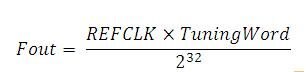
Method 4
The final method (and by far the best in my opinion) is using the Si570 IC produced by Silicon Labs. This amazing little chip is described as an “any rate I2C programmable crystal oscillator” and it does indeed live up to its claim. It contains a programmable crystal oscillator which is fed through two output dividers to give the frequency required, in terms of software, it is difficult to program but, for hardware, it only needs a 3.3V power supply and it will work. It can be hand soldered easily and a PCB is not needed. My first attempt used a blank sheet of circuit board, cut with a Stanley knife to provide isolation, and it worked fine. It also costs a lot less than DDS (£20 compared to £41 just for the DDS chip without the OXCO or the power supplies) so if it let out the magic smoke, it would be cheaper to replace. It also has no problems with spurs, but as it generates a square wave, it has strong odd harmonics. The other ‘quirk’ of the Si570 is that, to adjust the crystal frequency by more than 350ppm, the output has to be stopped which produces a little pop in the receiver audio.
As my time is more freely available than my money, and I wasn’t too bothered about the occasional pop in the audio, I decided to use the Si570. It communicates using the I2C bus on the Raspberry Pi and comes with individual factory calibration values, allowing the output calibrated to excellent accuracy without having to zero beat it to a frequency reference. A ‘quasi oven’ (Idea taken from the Genesis G59 SDR) was used to ensure the temperature of the Si570 did not vary too much, increasing frequency stability. With both DDS and Si570, the value for frequency used in calculations can be displayed(± any fixed frequency this was mixed with) so it does not have to be measured.
For more comparison of DDS vs Si570, see Hans Summers’ (G0UPL) fantastic web page on the subject, http://www.hanssummers.com/ddssi570.html . I was going to include the python code to control the Si570 but I have run out of time. So, next week, writing the python script to control the Si570 and a look at the circuit board.
