


OK, so continueing the series on PI 2 with windows 10 for IoT, I decided to create a demo app for the PiFace Digital II, there where no libraries for the primary chip on the board. The MCP23S17 SPI to 16 pin expander so I wrote my own, then put a cool UI ontop of it so I can play with the board under Windows 10.
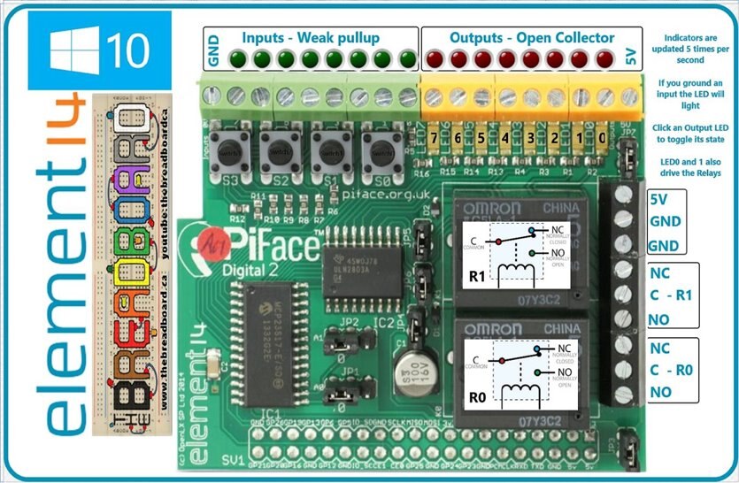
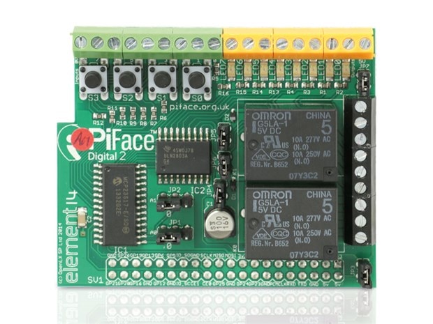
This is the PiFace II
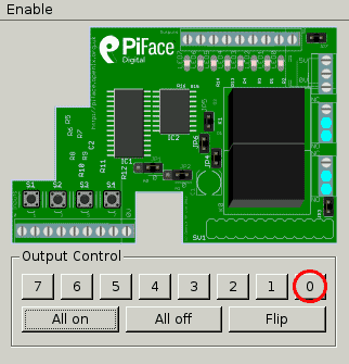
This is what the Linux UI Looks like
this is the my version
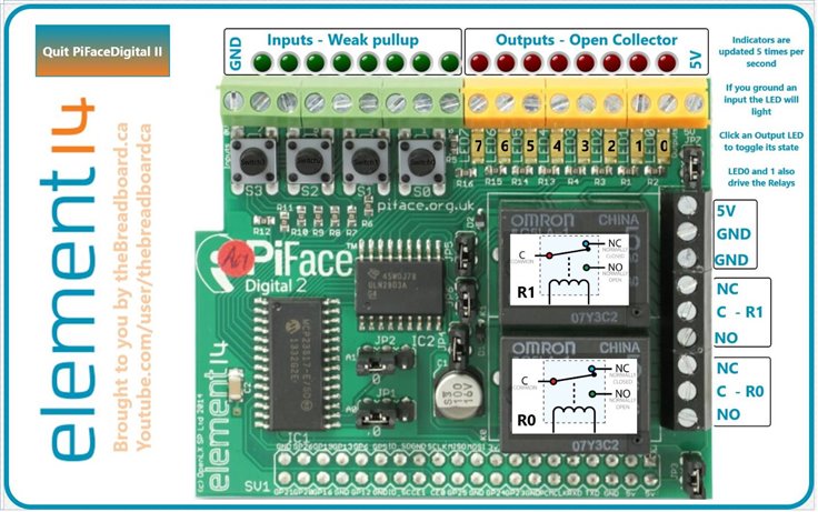
I like mine more 
You can use it by simply clicking on the relays (The graphics update to show the state of the contacts, the LED 0 through 7 or the 4 switches, they all work and actually drive the outputs (The switches simulate the button being pressed, im not that good ) but if you short the input to ground it is happily recognized and reflected in the state of one of the green indicators. Pushing hte real switches also works.Both the Inputs and the Putputs are monitored every 200mS and the virtual LEDS (Red and Green) are updated based on the bit pattern found
The inputs have a weak 100K pullup on them to V+ so all you need is a switch to ground and they will work, the outputs are either open collector or one of the two relays.
It should also be noted that even though the default for the PiFace is that the green pins are inputs, there is nothing stopping he coder setting some as an output and extending the range of features. My library supports this, the UI does not yet. I may add this in a future version
So this is a very short post as there is not a huge amount to say,, as its all int he software and the UI. you can download my Visual Studio project from here, you should be able to simply load it into Visual Studio Community edition and upload to your PI2 after seting its remote parameters of course
I have a video where I walk you through it all and this will be added tomorow as it is late here and it is still busy rendering
The MCP23S17 Class library is here fo rthose not wanting to wait for a download, there is a method to get most things done with it and you can use as you wish
using System;
using System.Collections.Generic;
using System.Linq;
using System.Text;
using System.Threading.Tasks;
using Windows.Devices.Spi;
using Windows.Devices.Enumeration;


namespace SPI_GPIO
{
    public class MCP23S17
    {


        private const byte IODIRA  = 0x00 ;    // I/O Direction Register
        private const byte IODIRB  = 0x01;      // 1 = Input (default), 0 = Output
        private const byte IPOLA    = 0x02 ;    // MCP23x17 Input Polarity Register
        private const byte IPOLB    = 0x03 ;    // 0 = Normal (default)(low reads as 0), 1 = Inverted (low reads as 1)
        private const byte GPINTENA = 0x04 ;    // MCP23x17 Interrupt on Change Pin Assignements
        private const byte GPINTENB = 0x05 ;    // 0 = No Interrupt on Change (default), 1 = Interrupt on Change
        private const byte DEFVALA  = 0x06  ;    // MCP23x17 Default Compare Register for Interrupt on Change
        private const byte DEFVALB  = 0x07 ;    // Opposite of what is here will trigger an interrupt (default = 0)
        private const byte INTCONA  = 0x08 ;    // MCP23x17 Interrupt on Change Control Register
        private const byte INTCONB  = 0x09 ;    // 1 = pin is compared to DEFVAL, 0 = pin is compared to previous state (default)
        private const byte IOCONA  = 0x0A ;    // MCP23x17 Configuration Register
        private const byte IOCONB  = 0x0B  ;    //    Also Configuration Register
        private const byte GPPUA    = 0x0C ;    // MCP23x17 Weak Pull-Up Resistor Register
        private const byte GPPUB    = 0x0D ;    // INPUT ONLY: 0 = No Internal 100k Pull-Up (default) 1 = Internal 100k Pull-Up
        private const byte INTFA    = 0x0E ;    // MCP23x17 Interrupt Flag Register
        private const byte INTFB    = 0x0F  ;    // READ ONLY: 1 = This Pin Triggered the Interrupt
        private const byte INTCAPA  = 0x10  ;    // MCP23x17 Interrupt Captured Value for Port Register
        private const byte INTCAPB  = 0x11  ;    // READ ONLY: State of the Pin at the Time the Interrupt Occurred
        private const byte GPIOA    = 0x12;      // MCP23x17 GPIO Port Register
        private const byte GPIOB    = 0x13;      // Value on the Port - Writing Sets Bits in the Output Latch
        private const byte OLATA    = 0x14;      // MCP23x17 Output Latch Register
        private const byte OLATB    = 0x15;      // 1 = Latch High, 0 = Latch Low (default) Reading Returns Latch State, Not Port Value!


        public const byte On = 1;
        public const byte Off= 0;
        public const byte Output= 0;
        public const byte Input = 1;


        private const byte Address = 0x00;  // offset address if hardware addressing is on and is 0 - 7 (A0 - A2)
        private const byte BaseAddW = 0x40;  // MCP23S17 Write base address
        private const byte BaseAddR = 0x41;  // MCP23S17 Read Base Address
        private const byte HAEN    = 0x08;  // IOCON register for MCP23S17, x08 enables hardware address so sent address must match hardware pins A0-A2


        private static UInt16 PinMode = 0XFFFF;    // default Pinmode for the MXP23S17 set to inputs
        private static UInt16 PullUpMode = 0XFFFF;    // default pullups for the MXP23S17 set to weak pullup
        private static UInt16 InversionMode = 0X0000;    // default invert to normal
        private static UInt16 PinState = 0X0000;    // default pinstate to all 0's


        /*RaspBerry Pi2  Parameters*/
        private const string SPI_CONTROLLER_NAME = "SPI0";  /* For Raspberry Pi 2, use SPI0                            */
        private const Int32 SPI_CHIP_SELECT_LINE = 0;      /* Line 0 maps to physical pin number 24 on the Rpi2, line 1 to pin 26        */


        private static byte[] readBuffer3 = new byte[3]; /*this is defined to hold the output data*/
        private static byte[] readBuffer4 = new byte[4]; /*this is defined to hold the output data*/
        private static byte[] writeBuffer3 = new byte[3];//register, then 16 bit value
        private static byte[] writeBuffer4 = new byte[4];//register, then 16 bit value


        private static SpiDevice SpiGPIO;
        public static async Task InitSPI()
        {
            try
            {
                var settings = new SpiConnectionSettings(SPI_CHIP_SELECT_LINE);
                settings.ClockFrequency = 1000000;// 10000000;
                settings.Mode = SpiMode.Mode0; //Mode0,1,2,3;  MCP23S17 needs mode 0


                string spiAqs = SpiDevice.GetDeviceSelector(SPI_CONTROLLER_NAME);
                var deviceInfo = await DeviceInformation.FindAllAsync(spiAqs);
                SpiGPIO = await SpiDevice.FromIdAsync(deviceInfo[0].Id, settings);
            }


            /* If initialization fails, display the exception and stop running */
            catch (Exception ex)
            {
                //statusText.Text = "\nSPI Initialization Failed";
            }
        }


        public static void InitMCP23S17()
        {
            WriteRegister8(IOCONA, HAEN);                  // enable the hardware address incase there is more than one chip
            WriteRegister16(IODIRA, PinMode);                // Set the default or current pin mode


        }
        public static void WriteRegister8(byte register, byte value)
        {
            // Direct port manipulation speeds taking Slave Select LOW before SPI action
            writeBuffer3[0] = (BaseAddW | (Address << 1));
            writeBuffer3[1] = register;
            writeBuffer3[2] = value;
            try
            {
                SpiGPIO.Write(writeBuffer3);
            }


            /* If initialization fails, display the exception and stop running */
            catch (Exception ex)
            {
                //statusText.Text = "\nFailed to Wrie to DAC";
            }// Send the byte
        }
        public static void WriteRegister16(byte register, UInt16 value)
        {
            writeBuffer4[0] = (BaseAddW | (Address << 1));
            writeBuffer4[1] = register;
            writeBuffer4[2] = (byte)(value >> 8);
            writeBuffer4[3] = (byte)(value & 0XFF);
            try
            {
                SpiGPIO.Write(writeBuffer4);
            }


            /* If initialization fails, display the exception and stop running */
            catch (Exception ex)
            {
                //statusText.Text = "\nFailed to Wrie to DAC";
            }
        }

        // Set the pin mode a pin at a time or all 16 in one go
        // any value other then Input is taken as output
        public static void setPinMode(byte pin, byte mode)
        {
            if (pin > 15) return;              // only a 16bit port so do a bounds check, it cant be less than zero as this is a byte value
            if (mode == Input)
            {
                PinMode |= (UInt16)(1 << (pin));              // update the pinMode register with new direction
            }
            else
            {
                PinMode &= (UInt16)(~(1 << (pin)));            // update the pinMode register with new direction
            }
            WriteRegister16(IODIRA, PinMode);                // Call the generic word writer with start register and the mode cache
        }
        public static void setPinMode(UInt16 mode)
        {
            WriteRegister16(IODIRA, mode);
            PinMode = mode;
        }


        // Set the pullup a pin at a time or all 16 in one go
        // any value other than On is taken as off
        public static void pullupMode(byte pin, byte mode)
        {
            if (pin > 15) return;
            if (mode == On)
            {
                PullUpMode |= (UInt16)(1 << (pin));
            }
            else
            {
                PullUpMode &= (UInt16)(~(1 << (pin)));
            }
            WriteRegister16(GPPUA, PullUpMode);
        }
        public static void pullupMode(UInt16 mode)
        {
            WriteRegister16(GPPUA, mode);
            PullUpMode = mode;
        }


        // Set the inversion a pin at a time or all 16 in one go
        public static void InvertMode(byte pin, byte mode)
        {
            if (pin > 15) return;
            if (mode == On)
            {
                InversionMode |= (UInt16)(1 << (pin - 1));
            }
            else
            {
                InversionMode &= (UInt16)(~(1 << (pin - 1)));
            }
            WriteRegister16(IPOLA, InversionMode);
        }
        public static void InvertMode(UInt16 mode)
        {
            WriteRegister16(IPOLA, mode);
            InversionMode = mode;
        }


        // WRITE FUNCTIONS - BY WORD AND BY PIN


        public static void WritePin(byte pin, byte value)
        {
            if (pin > 15) return;
            if (value > 1) return;
            if (value == 1)
            {
                PinState |= (UInt16)(1 << pin);
            }
            else
            {
                PinState &= (UInt16)(~(1 << pin));
            }
            WriteRegister16(GPIOA, PinState);
        }
        public static void WriteWord(UInt16 value)
        {
            WriteRegister16(GPIOA, value);
            PinState = value;
        }


        // READ FUNCTIONS - BY WORD, BYTE AND BY PIN
        public static UInt16 ReadRegister16()
        {
            writeBuffer4[0] = (BaseAddR | (Address << 1));
            writeBuffer4[1] = GPIOA;
            writeBuffer4[2] = 0;
            writeBuffer4[3] = 0;
            SpiGPIO.TransferFullDuplex(writeBuffer4, readBuffer4);
            return convertToInt(readBuffer4);                            // Return the constructed word, the format is 0x(register value)
        }
        public static byte ReadRegister8(byte register)
        {        // This function will read a single register, and return it
            writeBuffer3[0] = (BaseAddR | (Address << 1));  // Send the MCP23S17 opcode, chip address, and read bit
            writeBuffer3[1] = register;
            SpiGPIO.TransferFullDuplex(writeBuffer3, readBuffer3);
            return readBuffer4[2]; // convertToInt(readBuffer);                            // Return the constructed word, the format is 0x(register value)
        }
        public static UInt16 ReadPin(byte pin)
        {
            if (pin > 15) return 0x00;                  // If the pin value is not valid (1-16) return, do nothing and return
            UInt16 value = ReadRegister16();                        // Initialize a variable to hold the read values to be returned
            UInt16 pinmask = (UInt16)(1 << pin);                        // Initialize a variable to hold the read values to be returned
            return ((value & pinmask) > 0) ? On : Off;  // Call the word reading function, extract HIGH/LOW information from the requested pin
        }


        private static UInt16 convertToInt(byte[] data)
    {
        // byte[0] = command, byte[1] register, byte[2] = data high, byte[3] = data low
        UInt16 result = (UInt16)(data[2] & 0xFF);
        result <<= 8;
        result += data[3];
        return result;
    }


}
}
Again like previous apps I have shared, when looking at each individual part, it is quite simple and always ends up in one of two methods, in this case "WriteRegister8" or "WriteRegister16",
The PDF for the chip on the PIFace can be found here and it is one consistently used by the PiFace series to drive their boards http://ww1.microchip.com/downloads/en/DeviceDoc/21952b.pdf
If I can get a hold of the new PiFace Digital boards hint hint spannerspencer , element14Dave I will update the app for those too as there very different to the one I have, I see there also stackable so the app should work with atleast a pair to cover the variations


