


GPIO Access
For some time now anyone with a Raspberry Pi and an add-on board has struggled with access to the unused GPIO pins.
Back when the PiFace Digital was first released, I suggested this as an option.
http://www.element14.com/community/roadTestReviews/1452
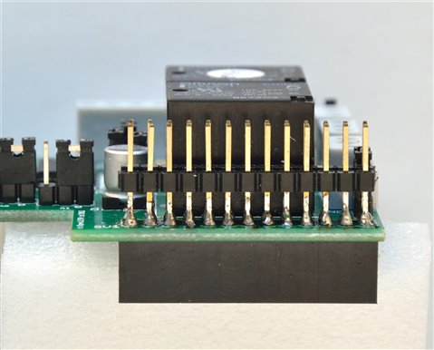
photo source 3 minions (me, myself and I)
While it suited at the time, adding the single row headers is not something that everyone can tackle, and access is only when you use that modified board.
Shortly afterwards the PiRack appeared.


photo source 3 minions (me, myself and I)
It allowed multiple PiFace Digitals (and some others) but the footprint was rather large.
PiFace Shim
So when I strumbled across this (and I do mean stumble as it didn't appear in subsequent searches), I ordered two.
PiFace SHIM GPIO Duplication Board for Raspberry Pi
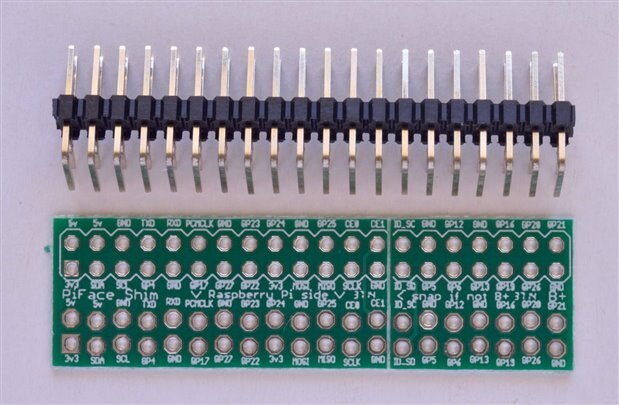
photo source 3 minions (me, myself and I)
It comes as a board and right angle header which you solder on.
If you simply want one or two GPIO, then you could forgo the 40 pin header and solder directly to the appropriate GPIO pins, or fit the number of pins required.
The design allows you to simply slip it over the GPIO pins then plug the add-on board on the original GPIO pins.
Access to all the GPIO is then available using the right angle header.
But I only have 26 pins on my RPi's. 
The manufacturer has wisely made it suitable for Model A, or B RPi with only 26 GPIO pins.
There is a break point (shown as a line across the board) which has been scored to assist snapping the board.
So problem solved ...or is it.? 
The holes that go over the GPIO have been staggered ever so slightly to ensure they make good contact.
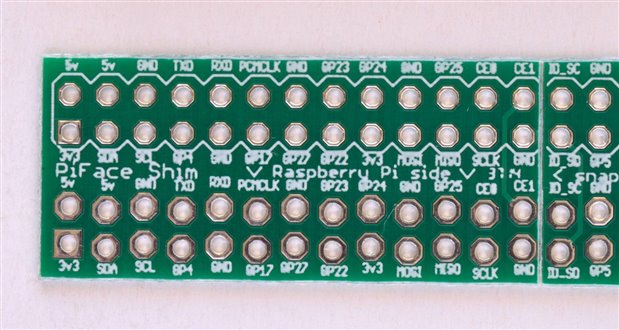
photo source 3 minions (me, myself and I) note the lower two rows ARE staggered.
I've seen this trick on some FTDI sockets on Arduino, meaning you don't have to have the header pins fitted to reprogram it.
BUT do they really give a decent contact.? 
For many of the GPIO you are dealing with voltage and extremely small currents, so any 'poor' contact joint would not be a problem.
However the power pins could cause problems.
So just be careful about what you want to hook onto the side.
I would not recommend trying to power the RPi via the right angle connector.
Cases
This solution certainly does give access, but depending on the case/enclosure, it might not fit.
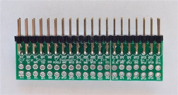
photo source 3 minions (me, myself and I)
Clearance
One of the other issues with the B+ and RPi2 is that the extra USB sockets get in the way of some of the add-on boards.
We discussed that here.
As you can see in the discussion, some add-on boards used the taller socket.
That got me thinking that if you soldered one of these.
https://www.adafruit.com/products/1979
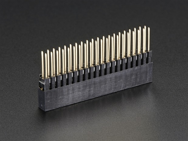
photo source www.adafruit.com
or one of these
https://www.adafruit.com/product/2223
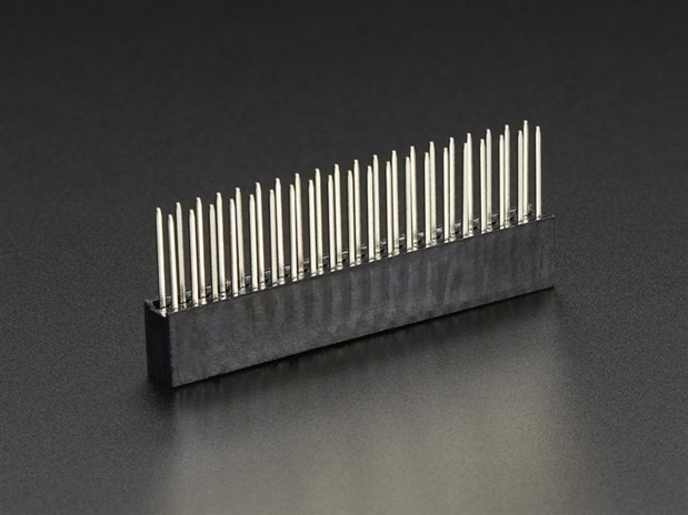
photo source www.adafruit.com
( Sorry element14 you still only have the 2x13 pin versions despite the B+ being out for some time .... )
to the connector then you certainly would have a better connection, and you fix the clearance issue ...
Does it work.?
Well that is a good question, since I only have a 2x13 (26 pin GPIO) stacking header, I couldn't try it
However I do need to order some parts, so I'll be sure to include some in with the order.
Enjoy
Mark

