element14 Community
element14 Community
    Register Log In
  • Site
  • Search
  • Log In Register
  • Members
    Members
    • Benefits of Membership
    • Achievement Levels
    • Members Area
    • Personal Blogs
    • Feedback and Support
    • What's New on element14
  • Learn
    Learn
    • Learning Center
    • eBooks
    • STEM Academy
    • Webinars, Training and Events
    • Learning Groups
  • Technologies
    Technologies
    • 3D Printing
    • FPGA
    • Industrial Automation
    • Internet of Things
    • Power & Energy
    • Sensors
    • Technology Groups
  • Challenges & Projects
    Challenges & Projects
    • Design Challenges
    • element14 presents
    • Project14
    • Arduino Projects
    • Raspberry Pi Projects
    • Project Groups
  • Products
    Products
    • Arduino
    • Dev Tools
    • Manufacturers
    • Raspberry Pi
    • RoadTests & Reviews
    • Avnet Boards Community
    • Product Groups
  • Store
    Store
    • Visit Your Store
    • Choose Another Store
      • Europe
      •  Austria (German)
      •  Belgium (Dutch, French)
      •  Bulgaria (Bulgarian)
      •  Czech Republic (Czech)
      •  Denmark (Danish)
      •  Estonia (Estonian)
      •  Finland (Finnish)
      •  France (French)
      •  Germany (German)
      •  Hungary (Hungarian)
      •  Ireland
      •  Israel
      •  Italy (Italian)
      •  Latvia (Latvian)
      •  
      •  Lithuania (Lithuanian)
      •  Netherlands (Dutch)
      •  Norway (Norwegian)
      •  Poland (Polish)
      •  Portugal (Portuguese)
      •  Romania (Romanian)
      •  Russia (Russian)
      •  Slovakia (Slovak)
      •  Slovenia (Slovenian)
      •  Spain (Spanish)
      •  Sweden (Swedish)
      •  Switzerland(German, French)
      •  Turkey (Turkish)
      •  United Kingdom
      • Asia Pacific
      •  Australia
      •  China
      •  Hong Kong
      •  India
      •  Korea (Korean)
      •  Malaysia
      •  New Zealand
      •  Philippines
      •  Singapore
      •  Taiwan
      •  Thailand (Thai)
      • Americas
      •  Brazil (Portuguese)
      •  Canada
      •  Mexico (Spanish)
      •  United States
      Can't find the country/region you're looking for? Visit our export site or find a local distributor.
  • Translate
  • Profile
Raspberry Pi
  • Products
  • More
Raspberry Pi
Blog Raspberry Pi 7” Capacitive Touch Display: Assembly and Enclosure
  • Blog
  • Forum
  • Documents
  • Events
  • Members
  • Mentions
  • Sub-Groups
  • Tags
  • More
  • Cancel
  • New
Raspberry Pi requires membership for participation - click to join
Blog Post Actions
  • Subscribe by email
  • More
  • Cancel
  • Share
  • Subscribe by email
  • More
  • Cancel
Group Actions
  • Group RSS
  • More
  • Cancel
Engagement
  • Author Author: shabaz
  • Date Created: 6 May 2016 6:21 AM Date Created
  • Views 4370 views
  • Likes 10 likes
  • Comments 15 comments
Related
Recommended
  • rpiintermediate
  • raspberry pi display
  • raspberry_pi_touchscreen
  • rpibeginner
  • raspberry_pi
  • rpi

Raspberry Pi 7” Capacitive Touch Display: Assembly and Enclosure

shabaz
shabaz
6 May 2016

Introduction

A while back a RaspberryPi.org-designed 7-inch Display with Capacitive Touch Capability7-inch Display with Capacitive Touch Capability was released; I decided to assemble it into an enclosureenclosure. This blog post documents the steps I took, including how to connect the Pi to the capacitive touch display.


The enclosure is very nicely made. It is not moulded but is instead composed from cut and heat-folded polystyrene material. Unlike some other enclosures, it has rounded/finished smooth edges and looks pretty good.

image


40-Pin Header Access

I wanted the enclosure to provide full access to the 40-way connector on the Pi. To achieve this, drill and cut/file the enclosure to the dimensions shown in the photo here.

image


The hole will provide easy access to the connector once it is finally assembled. A heat sink would be an excellent idea too.

image


Assembling the LCD Panel Interface Board and Pi

The LCD panel has an interface board on the back. While assembling stuff it is important that some care is taken not to accidentally unplug the touchscreen flex PCB; it is in a vulnerable position!

image


There are various connections on the LCD interface board but just a few are used for full functionality. The remainder are “spare”.

image


The first step is to get the flat flex cable (FFC) connector attached to the LCD display. The connector has opened and closed positions. To open it, the connector needs to be gently pulled from the sides. Observe the photo below, and the inset images, to see where to pull on the connector to open it. Slide in the flat flex cable (just a small amount of force is needed for this connector) about 4mm, check it is nicely squared and not at an angle, and then carefully push the connector sides back into the closed position.

image


After assembly inspect it to ensure that it is still all squared. It should look like the photo above (and close-up below).

image


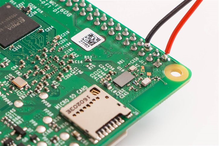
The display will be powered from the Pi (i.e. a single USB supply will be plugged into the Pi when it is all complete. There are other options but this is the most straightforward approach and is compatible with recent Pi models). To achieve that, jumper cables will be used to pass power from the Pi to the display. Plug the red and black ones into the +5V and 0V(GND) connections on the display board single-in-line (SIL) header connector.

image


The other ends will plug onto the Pi’s 40-way header, to pins 2 and 6 respectively. Notice in the diagram here that the pin numbering is in a zig-zag fashion, with pin 1 at the lower-right, and then pin 2 is at the lower-left. The pins to use are circled in red and black on the diagram, and they are pins 2 and 6.

image


However, I wanted the 40-way connector kept clean and empty for future expansion. So, with warranty-voiding tools in hand, I cut the jumper cables in half and soldered the connections to the underside and then checked for shorts with a multimeter.

image


The connections were secured with epoxy glue and then the Pi was screwed on top. You probably want to insert the SD card just before this point (it is easier with the board unscrewed). If you have a recent Raspbian software image then the display and touch capability will work with no additional configuration needed.

image


The display connector on the Pi needs to be opened in a similar way as with the earlier connector, but this time pulling the connector open vertically. See the photo below.

image


The flat cable should slide in with zero force, and then the connector can be pushed back to the closed position. Again, check that it is in perfectly square, and not at an angle.

image


Fitting the Enclosure

The plastic enclosure is in two pieces. The front border part, and the rear part.

The LCD panel is asymmetrical and will therefore only fit the front border part of the enclosure in a particular orientation.

image


By examining the plastic, you will see that one side has a second recess which is for the LCD glass to sit inside. Take off the protective film from the front border plastic and then it should fit snugly in place. It is a millimetre-perfect fit. The LCD bezel will sit exactly flush with the front side of the plastic border part of the enclosure.

image


At this stage an issue was discovered. The rear of the enclosure would dig against the touchscreen flex PCB enough to force out the flex from the connector and bend it at a sharp 90 degree angle in a shear type action against the PCB. I knew I would have to hack away at the enclosure but I didn’t know by how much. The result was ugly (I couldn’t easily clamp in place, and I just used a dremel style handheld tool hence the ugliness). Anyway, this is not visible.

image


After this the rear part of the enclosure fitted very well and the supplied screws were used. You probably only want to gently screw it in first, and power up and check that the display works, but also the touch capability functions. If touch capability does not work then probably the orange flex PCB has become unplugged. Open up the enclosure, pull the connector to the open position, insert the flex and then push the connector into the closed position.


Upside-Down Situation

This isn’t the end of the story! The Pi foundation made a mistake when it designed the LCD; the LCD was used up-side down! It was advertised as a very high quality display yet clearly the displayed images had extremely poor viewing angles. In a later software image the default view was inverted to try to repair the issue but it meant that manufacturers now had designs which expected the LCD to be mounted the initial way. The ‘bodge’ fix was to invert the image back in software, but it leaves users with poor viewing angles. Some vendors still show clearly incorrect images on their websites; I don’t know if they have not resolved the issue or just have misleading photos. Basically if you can see the orange flex PCB at the top, then the display is in the non-optimal, incorrect orientation. Turn it such that the orange flex PCB is at the bottom and that will have correct viewing angles.

image


The solution for this enclosure was to create a new stand to hold it the correct way up, to benefit from the best viewing angles. Two pieces of material (I used wood; plastic might be nicer) were cut to 55x30mm (the thickness can be around 6-10mm) and then an angle was cut as shown and then epoxied into position.

image

A side benefit of this fix is that if desired the entire unit can also be tipped to stand on all four points, for a horizontal layout.

image


Summary

Although it took a few hours of effort the results could be worth it. There is easy access to the 40-way GPIO header connector, and good viewing angles.

image

  • Sign in to reply

Top Comments

  • DAB
    DAB over 6 years ago +2
    Excellent detailed post. You did a great job of getting all of the useful bits accessible and still come out with a nice simple implementation. Well done. DAB
  • balearicdynamics
    balearicdynamics over 6 years ago in reply to shabaz +2
    LoL !!! I see that at the moment they have about 600 in stock. I need about 3 years to sell the same quantity of my full 3D printed project (but cost less) Enrico
  • shabaz
    shabaz over 6 years ago in reply to balearicdynamics +2
    Hi! Yeah the spirit is lost using an off-the-shelf enclosure when one could be self-made. It does look nice though, but is expensive. I think this design and your kiosk-mode design is way better than the…
  • hobantech
    hobantech over 2 years ago

    Thanks for the advice on soldering the GPIO. Here are some pics of the build.imageimage

    Allo digione signature - HiFi audio transport

    Raspberry pi 4 8G with usb microphone

    7" monitor.and frame

    Schiit Modi DAC


    Mike

    • Cancel
    • Vote Up +1 Vote Down
    • Sign in to reply
    • More
    • Cancel
  • shabaz
    shabaz over 4 years ago in reply to carter_v

    Hi Vic,


    I don't know the answer, but it could be something to do with the retropie image. Is this an install of retropie on top of Raspbian, or was it a pre-built retropie that doesn't require Raspbian to be installed beforehand? (I've not installed it, I'm just speculating).

    Raspbian should contain the drivers for this particular display mentioned in the blog post, it is part of the official software image. However, if there is some pre-built complete Retropie image that doesn't install on top of Raspbian, then possibly there could be some driver bug perhaps. It is possible to check by loading Raspbian only on a micro SD card, and seeing if you get the same enlarged screen issue. That will narrow down the problem.

    • Cancel
    • Vote Up 0 Vote Down
    • Sign in to reply
    • More
    • Cancel
  • carter_v
    carter_v over 4 years ago

    I just recently purchased one of these monitors and I cannot get the image to fit the screen. It seems to be extremely enlarged and I can only see the top left of the display. I do have bezels on the image I don't know if that has anything to do with it but the bezels and everything or display properly but the actual image of the game in retropie does not fit the space in the center it just shows it very enlarged and only the left top corner

    • Cancel
    • Vote Up 0 Vote Down
    • Sign in to reply
    • More
    • Cancel
  • COMPACT
    COMPACT over 5 years ago

    It was made for us Down Under!

    • Cancel
    • Vote Up 0 Vote Down
    • Sign in to reply
    • More
    • Cancel
  • DAB
    DAB over 5 years ago

    Very nice build.


    DAB

    • Cancel
    • Vote Up 0 Vote Down
    • Sign in to reply
    • More
    • Cancel
>
element14 Community

element14 is the first online community specifically for engineers. Connect with your peers and get expert answers to your questions.

  • Members
  • Learn
  • Technologies
  • Challenges & Projects
  • Products
  • Store
  • About Us
  • Feedback & Support
  • FAQs
  • Terms of Use
  • Privacy Policy
  • Legal and Copyright Notices
  • Sitemap
  • Cookies

An Avnet Company © 2023 Premier Farnell Limited. All Rights Reserved.

Premier Farnell Ltd, registered in England and Wales (no 00876412), registered office: Farnell House, Forge Lane, Leeds LS12 2NE.

ICP 备案号 10220084.

Follow element14

  • Facebook
  • Twitter
  • linkedin
  • YouTube