







|

Abstract: I recently acquired a Motorola Atrix Lapdock and tried to get it working with my RasPi. Unfortunately, something was wrong with the micro HDMI cable, specifically some cheap HDMI cables do not implement the individual ground lines. I came up with a temporary work-around. I thought people might be interested in the combination of detective work and exploration that got me to the solution. Also, some of the Lapdock analysis I did may be useful to others.
I first read about the Motorola Atrix Lapdock quite a few months ago. It's a really neat idea, to use a smart phone as a motherboard to make a laptop computer with "good enough" performance. I suspect it failed to catch on for two reasons: (1) the list price of US$500 was way too much for the capabilities and (2) the smart phone software was unsuitable for a laptop. I suspect it's primarily the software problem -- so many promising technologies have been sunk because the software isn't there in time. So Motorola remaindered them, and grateful tinkerers have benefited from Motorola's optimism.
I had thought of using Lapdock for RasPi, but I couldn't find enough technical information to tell if it was possible and I wasn't willing to fork over US$100 for something that might have been impossible to interface. So I was very glad to see Drew Fustini's element14 'blog Raspberry Pi laptop. I was especially glad that he listed sources for the unusual Micro HDMI and USB adapters and cables.
So I ordered a Lapdock along with the cables and adapters that Drew recommended, including a short USB A male to A male adapter as in Update #2. I ordered a Micro HDMI D male to HDMI A male cable that was different from Drew's. They're all the same, right?
I was very impressed by Lapdock when it arrived. It's a very beautiful piece of equipment. Internally it's quite complex with lots of cable assemblies, tiny circuit boards, and specialized mechanical hardware. I can see why Motorola orginally charged US$500 for it.
When the cables arrived from China, I eagerly charged up my Lapdock and attached the cables. Well, it didn't work. I didn't want to send the Lapdock back, since I didn't know if the problem was the Lapdock or one of the HDMI cables or adapters. I was easily able to test the USB cables and adapters -- they were fine.
There's a lot of useful information about how Lapdock works in Drew's 'blog and its links. There's also a long thread on the subject at raspberrypi.org called "I made a Raspberry PI Laptop". From veryevil [5 June 2012] and Lob0425 [20 July 2012] I learned that you must connect an HDMI source to Lapdock for it to power on and provide +5V on the micro USB connector. Nick S [30 June 2012] posted some very nice photos of Lapdock internals, including this one of the high-density 30-pin JHDMI receptacle that has the Micro HDMI and USB signals. In that same photo you can see the 30-pin mating plug that's at the end of a small (and probably expensive) cable assembly. Those are tiny connectors -- I think they're 1 mm pitch. [Update: wrong by a factor of two: they're 0.5 mm  ]
]
ARMed with this information, I took a look inside my Lapdock -- with power supply / battery charger disconnected, of course. I figured I had already voided any warranty by hooking up non-Motorola cables, so what did I have to lose? (Speaking of warranties, if you want to try this at home my comments here come with no warranty. Proceed at your own risk!) Lapdock is actually pretty easy to disassemble -- you only need to take off the small strip in the back of the Lapdock and it's held on by three small screws (two under pry-off rubber feet) and some plastic tabs that I managed to unhook without breaking anything off. You get good quality for US$500.
There is a plastic shield over part of the circuit board. It is there for a good reason. Under it are direct connections to the 12V battery and it's really easy to short those points to ground "mit Spitzensparken". So leave the shield in place. Also, power is on unless you disconnect the cable that goes to the battery. I was afraid to disconnect this cable, so I worked with 12V power on and stayed away from the shielded areas.
So where to begin? Well, the 30-pin JHDMI receptacle is a good starting point since that's where the HDMI cable attaches. The 30-pin plug comes off easily it you gently pry the edge with a small screwdriver. Next it's time to start probing with a multimeter. Always start with volts. A voltmeter is high impendance so you're less likely to damage something than if you use an ohmmeter or ammeter setting. The two USB A ports have nicely grounded shells, so that's a good place for the black lead on the voltmeter.
Here's a close-up of the first JHDMI pins. The magnifier is trade show swag from Coilcraft. Pin 1 is marked with a triangle and there are tick marks every 5 pins. (Thank you very much, whoever did the excellent Lapdock PCB layout.)
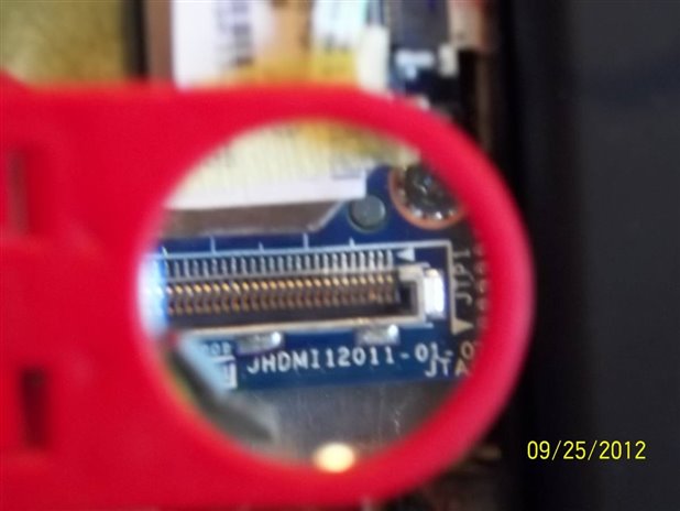
As expected, most of the 30 pins were 0V. After all, Lapdock is powered off. But JHDMI pin 3 was around 10 volts! WTF? Who in their right mind would have 10V on a pin that connects to 5V or 3.3V equipment? OK, must be a defective Lapdock.
At this point serendipity occurred. I happened to have a USB tester dongle plugged into one of the Lapdock USB A ports. This was so I could easily get at the USB Vbus and Gnd without shorting to the shell. This USB dongle (shown below) was another bit of trade show swag, this time from Softeq Development. When you plug it into a live USB port, the LEDs light up bright blue. Really bright.
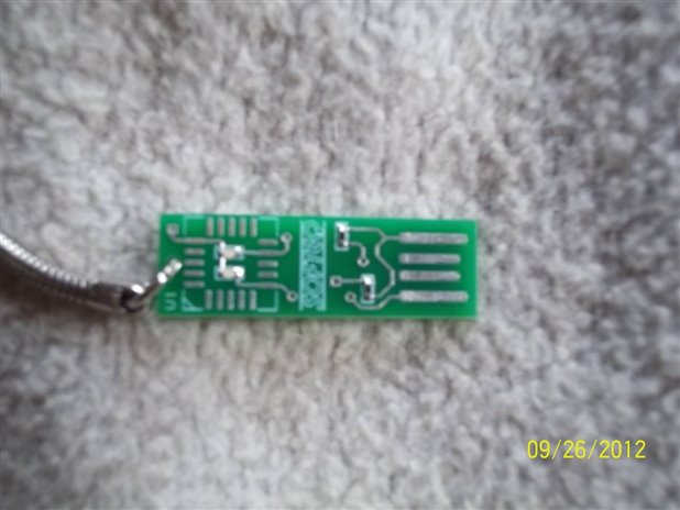
When I was testing JHDMI pin 3, at one point my probe accidentally touched JHDMI's shield and guess what? The USB dongle LEDs flashed -- just for a moment. I tried it again and they did the same thing -- just a momentary flash. This was the first evidence that I was making real progress, because it meant that Lapdock was energizing 5V at least momentarily. Using a sillyscope, I discovered that Lapdock was turning on sometimes for 18 msec, sometimes 47 msec.
If I'm going to have 10V running around, I sure hope it's current-limited. I tried grounding pin 3 through an ammeter. Sure enough, I got the same flashes and the current was around 64 uA. This means that there's a 160K pull-up resistance to 10V. I'm still leery about 10V running around, but at least it's such low current that as long as your HDMI device has proper diode clamps you won't damage it.
So where is JHDMI pin 3 connected to the Micro HDMI and USB connectors? Well I decided to go through the long process of analyzing the cable assembly that connects JHDMI to the Micro HDMI and USB connectors. In hindsight, this was not needed to solve my problem of getting Lapdock running, but I didn't know what the solution was going to be and I wanted to rule out other possibilities. So using an ohmmeter setting and a safety pin so I could probe tiny micro HDMI contacts, here is what I came up with. The first number on each line is the JHDMI pin. HDMI pins are designated Ax for full-size type A and Dx for Micro type D. Wikipedia lists the HDMI signals -- they're also in a white paper from HDMI Licensing. The cable assembly shorts the HDMI connector shell to all the individual HDMI grounds pins except for DDC/CEC ground.
1 HDMI A19/D1 = hot plug
2 HDMI ground
3 HDMI A17/D16 = DDC/CEC ground
4 HDMI ground
5 HDMI A16/D18 = SDA
6 HDMI A15/D17 = SCL
7 HDMI ground
8 HDMI A12/D14 = Clock-
9 HDMI A10/D12 = Clock+
10 HDMI ground
11 HDMI A1/D3 = Data 2+
12 HDMI A3/D5 = Data 2-
13 HDMI ground
14 HDMI A4/D6 = Data 1+
15 HDMI A6/D8 = Data 1-
16 HDMI ground
17 HDMI A7/D9 = Data 0+
18 HDMI A9/D11 = Data 0-
19 unknown
20 HDMI A18/D19 = +5V
21 unknown
22 USB 2 = D-
23 USB 3 = D+
24 USB shield (shorted to HDMI ground)
25 USB 4 = ID
26 USB 5 = GND (not shorted to HDMI ground)
27 unknown
28 unknown
29 USB 1 = Vbus
30 USB 1 = Vbus
I hope this is right. Please leave a comment if you find something different.
So here's the deal: all HDMI grounds are shorted to the HDMI shell except the DDC/CEC ground which is connected to JHDMI pin 3. If nothing is plugged into the Lapdock Micro HDMI port, Lapdock pulls DDC/CEC ground to +10V. Then when you plug an Atrix into Lapdock, Atrix shorts DDC/CEC ground to the other grounds, and Lapdock detects that Atrix is present and brings up the +5V charging voltage on the Micro USB connector. If Lapdock is open, it also turns on the two USB A ports and turns on the display, keyboard, and trackpad.
The same things happen if you hook up a Raspberry Pi through HDMI and USB cables -- provided that the HDMI cable implements the DDC/CEC ground wire. However, not all HDMI cables are the same. A lot of cheap HDMI cables do not implement the individual ground signals. Instead, they just have a common foil shield that's connected to the connector shells at both ends. This works in most HDMI applications, but if your application requires individual ground lines -- like Lapdock -- it won't work.
(I found out about this early this year when I was trying to hook up my rev B4 BeagleBoard through a cheap HDMI cable. After trying everything short of surgery, I finally opened up one of the cheap HDMI cables and verified that they hadn't bothered to include the individual grounds. It turns out that rev B4 BeagleBoard did not ground the shell for reasons nobody remembers. I attached a ground line to BeagleBoard's HDMI shell and it works fine with cheap cables.)
OK, so now I understand why my Lapdock didn't work with my RasPi. The problem is that getting a replacement cable takes time and there's no guarantee that the next one won't have the same problem. Since I wanted to bring my new Lapdock to RasPi's USA Hackspace Tour in San Francisco this coming Saturday, I decided to fix it the Hacker Way. Since JHDMI pin 3 is right next to ground pin 4, I added a tiny solder bridge between the two pins. So my Lapdock now thinks there's always an HDMI cable attached and works great with RasPi. I added a switch to USB +5V to prevent power from getting to RasPi when Lapdock is closed.
Now, there's a little problem with doing it this way: battery discharge. By grounding pin 3, I have a constant 64 uA draining from the battery. It's not a lot, but it will discharge the battery faster than it would without it. Also, Micro USB +5V is now constantly active. With RasPi switched off, the +5V switcher isn't producing any output current, but the switcher's quiescent current is not zero and adds to the battery drain.
At some point, I want to install a tiny switch near Lapdock's Micro HDMI and USB connectors and use it to ground JHDMI pin 3. When I do that, it will power off Lapdock completely and I won't need the +5V power switch on RasPi any more. The problem is that I need to access a PCB trace that connects to JHDMI pin 3. As far as I know, it's not accessible on the top surface but I bet I can find it on the bottom surface. There has to be a 160K pull-up resistor there somewhere, and I should be able to attach to it. But I'll watch the Engadget tear-down carefully first.
One thing I'm puzzled by is why the Lapdock USB A ports are energized when you connect HDMI with the lapdock closed. Is Lapdock taking a long time to detect that it's closed and assumes it's open when first powered up?
Update 3 October 2012: I've installed a tiny toggle switch to ground JHDMI pin 3, so now when Lapdock is off it's no longer draining 64 uA from the battery along with whatever it uses to generate +5V for the Micro USB connector. As a bonus, with the new switch in place, I no longer need a switch for RasPi USB +5V.
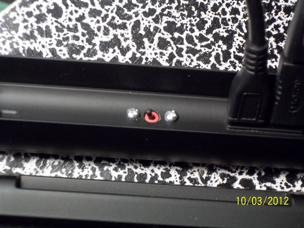
I had originally thought of attaching a wire to JHDMI pin 3 by finding a suitable spot on the bottom of the Lapdock PCB, but I soon realized that it would be better to attach to the Lapdock cable that goes between JHMDI and the Lapdock micro HDMI and micro USB connectors. This way I avoid Lapdock PCB modifications.
It's fairly easy to peel back the shielding tape from the JHDMI end of the cable, exposing the wires that connect to the micro HDMI connector. I only exposed wires at the pin 1 end. Here's the best photo I could manage:
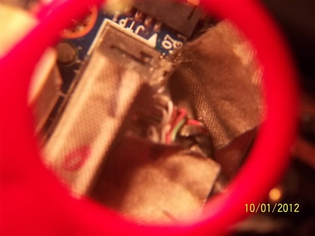
The wires are very thin, so be very careful not to break any. I found some good photos of the other (Micro HDMI) end of the cable at "Raspberry Pi (modding Atrix Lapdock)", which helped confirm wire colors. I believe these are the wires for JHDMI pins 1-7:
1 HDMI A19/D1 = hot plug (black)
2 HDMI ground (white)
3 HDMI A17/D16 = DDC/CEC ground (brown)
4 HDMI ground (white)
5 HDMI A16/D18 = SDA (red)
6 HDMI A15/D17 = SCL (green)
7 HDMI ground (white, IIRC)
I scraped insulation off the brown wire and verified that it did indeed connect to JHDMI pin 3. Then I carefully cut it and soldered it to a longer (red) wire going to one side of the switch. I connected a (black) ground wire from the other side of the switch to the micro HDMI shielding tape by inserting it under the plate that holds the micro HMDI and micro USB connectors in place.
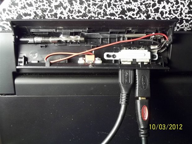
I used a C&K GT02 sealed ultraminiature SPST toggle switch I had in my spare parts collection. This is was designed for PCB mounting, but I was able to bend the mounting pins 90 degrees so I could hold the switch in place with #2-56 screws. There's actually quite a bit of room in there, as you can see.
I didn't need to label the toggle switch. It's left off when you're done using RasPi, and right on when it's time to create.
[This blog entry is copyright 2012 John F. Beetem and is licensed under the Creative Commons Attribution-ShareAlike 3.0 Unported License (CC BY-SA 3.0). To view a copy of this license, visit http://creativecommons.org/licenses/by-sa/3.0/. No warranty is expressed or implied.]
| Product Name* | Description | Supplier | ||
| Raspberry Pi Model BRaspberry Pi Model B | Raspberry Pi model B | Raspberry Pi |
| |
| Optical MouseOptical Mouse | Basic USB optical mouse | IONE / Pro Signal |
| |
| Raspberry Pi Power SupplyRaspberry Pi Power Supply | 120-240v to 5V power supply with micro USB connector | Raspberry Pi |
| |
| KeyboardKeyboard | Basic USB keyboard | Gear Head / A4 Tech |
| |
| Pre-Programmed 4GB SD CardPre-Programmed 4GB SD Card | 4GB Class 4 SD card preloaded with Debian 6 Linux | Samsung |
| |
| Adafruit Pi CobblerAdafruit Pi Cobbler | GPIO breakout kit for Raspberry Pi | Adafruit Industries |
| |
| BreadboardBreadboard | Basic breadboard with 830 connection points | Twin Industries |
| |
| Jumper wire bundleJumper wire bundle | Jumper wires for use on breadboard | Bud Industries |
| |
| FTDI USB-Serial CableFTDI USB-Serial Cable | 3.3v USB to serial interface cable | FTDI |
|
*Products and resources listed are listed to help members build their own Pi Projects. They are suggestions and listed for educational purposes. For substitutions of any parts, please post a question asking the original author.
Top Comments