element14 Community
element14 Community
    Register Log In
  • Site
  • Search
  • Log In Register
  • Members
    Members
    • Benefits of Membership
    • Achievement Levels
    • Members Area
    • Personal Blogs
    • Feedback and Support
    • What's New on element14
  • Learn
    Learn
    • Learning Center
    • eBooks
    • STEM Academy
    • Webinars, Training and Events
    • Learning Groups
  • Technologies
    Technologies
    • 3D Printing
    • FPGA
    • Industrial Automation
    • Internet of Things
    • Power & Energy
    • Sensors
    • Technology Groups
  • Challenges & Projects
    Challenges & Projects
    • Design Challenges
    • element14 presents
    • Project14
    • Arduino Projects
    • Raspberry Pi Projects
    • Project Groups
  • Products
    Products
    • Arduino
    • Dev Tools
    • Manufacturers
    • Raspberry Pi
    • RoadTests & Reviews
    • Avnet Boards Community
    • Product Groups
  • Store
    Store
    • Visit Your Store
    • Choose Another Store
      • Europe
      •  Austria (German)
      •  Belgium (Dutch, French)
      •  Bulgaria (Bulgarian)
      •  Czech Republic (Czech)
      •  Denmark (Danish)
      •  Estonia (Estonian)
      •  Finland (Finnish)
      •  France (French)
      •  Germany (German)
      •  Hungary (Hungarian)
      •  Ireland
      •  Israel
      •  Italy (Italian)
      •  Latvia (Latvian)
      •  
      •  Lithuania (Lithuanian)
      •  Netherlands (Dutch)
      •  Norway (Norwegian)
      •  Poland (Polish)
      •  Portugal (Portuguese)
      •  Romania (Romanian)
      •  Russia (Russian)
      •  Slovakia (Slovak)
      •  Slovenia (Slovenian)
      •  Spain (Spanish)
      •  Sweden (Swedish)
      •  Switzerland(German, French)
      •  Turkey (Turkish)
      •  United Kingdom
      • Asia Pacific
      •  Australia
      •  China
      •  Hong Kong
      •  India
      •  Korea (Korean)
      •  Malaysia
      •  New Zealand
      •  Philippines
      •  Singapore
      •  Taiwan
      •  Thailand (Thai)
      • Americas
      •  Brazil (Portuguese)
      •  Canada
      •  Mexico (Spanish)
      •  United States
      Can't find the country/region you're looking for? Visit our export site or find a local distributor.
  • Translate
  • Profile
Raspberry Pi
  • Products
  • More
Raspberry Pi
Blog Raspberry Pico as USB test device - part 2: a working USBTMC compliant instrument
  • Blog
  • Forum
  • Documents
  • Events
  • Members
  • Mentions
  • Sub-Groups
  • Tags
  • More
  • Cancel
  • New
Raspberry Pi requires membership for participation - click to join
Blog Post Actions
  • Subscribe by email
  • More
  • Cancel
  • Share
  • Subscribe by email
  • More
  • Cancel
Group Actions
  • Group RSS
  • More
  • Cancel
Engagement
  • Author Author: Jan Cumps
  • Date Created: 3 Feb 2023 10:45 AM Date Created
  • Views 433 views
  • Likes 11 likes
  • Comments 7 comments
Related
Recommended
  • raspberry
  • pico_usbtmc_scpi
  • pico
  • scpi

Raspberry Pico as USB test device - part 2: a working USBTMC compliant instrument

Jan Cumps
Jan Cumps
3 Feb 2023
Raspberry Pico as USB test device - part 2: a working USBTMC compliant instrument

There's a standard profile for USB test and measurement devices, called USBTMC. If your instrument supports it, it becomes a plug-and-play device for the likes of LabVIEW. The Raspberry Pico examples come with a set of TinyUSB profile examples, and USBTMC is one of them. In this post, developed an USBTMC and SCPI compliant instrument on a Pico. 

image

At the end of the blog you'll find the VSCode project with source and binaries, of a working USBTMC of my previous USB-Serial lab programmable instrument.

Turn the TinyUSB USBTMC demo code into a real SCPI parser

In my original project, a few months ago (link in the blog header), I made a programmable lab switch. SCPI traffic was over serial, either via UART or the USB as COM port. That works well, and test applications like LabVIEW and pyvisa support it.
But there's a standard profile for measurement & test devices: USBTMC, so let's try & learn.

This project offers the same functionality as my original serial/usb firmware: control a number of output pins via SCPI. The only things that changes in the firmware is the interaction between TinyUSB and the SCPI parser.
I stayed as close as possible to the TinyUSB USBTMC example, so that it's easy to see how simple the combination SPI-Parser / USBTMC can be.
There's one other change: my original project uses FreeRTOS, this one is bare metal. I did that to keep the similarity to the TinyUSB example intact.

The TinyUSB USBTMC example

The TinyUSB example supports one SCPI command: *IDN?. When it detects that this command is received, the example sends a predefined reply back. Here is where this happens:

static const char idn[] = "TinyUSB,ModelNumber,SerialNumber,FirmwareVer123456\r\n";
static volatile uint8_t status;

// 0=not query, 1=queried, 2=delay,set(MAV), 3=delay 4=ready?
// (to simulate delay)
static volatile uint16_t queryState = 0;
static volatile uint32_t queryDelayStart;
static volatile uint32_t bulkInStarted;
static volatile uint32_t idnQuery;

bool tud_usbtmc_msg_data_cb(void *data, size_t len, bool transfer_complete)
{
  // ...
  if(transfer_complete && (len >=4) && !strncasecmp("*idn?",data,4))
  {
    idnQuery = 1;
  }
  // ...
}

void usbtmc_app_task_iter(void) {
  switch(queryState) {
  // ...
  case 4: // time to transmit;
    if(bulkInStarted && (buffer_tx_ix == 0)) {
      if(idnQuery)
      {
        tud_usbtmc_transmit_dev_msg_data(idn,  tu_min32(sizeof(idn)-1,msgReqLen),true,false);
        queryState = 0;
        bulkInStarted = 0;
      }
      else
      {
        buffer_tx_ix = tu_min32(buffer_len,msgReqLen);
        tud_usbtmc_transmit_dev_msg_data(buffer, buffer_tx_ix, buffer_tx_ix == buffer_len, false);
      }
      // MAV is cleared in the transfer complete callback.
    }
    break;
    // ...
  }
}

In this example, the firmware sets a status when it receives a recognised request. It only knows *IDN?, the SCPI "hello, world!").  When the example receives this command, and it's ready to reply (input handling complete), it sends the string "TinyUSB,ModelNumber,SerialNumber,FirmwareVer123456\r\n" back. An ideal example to check if the Pico enumerates as a test device, and to validate that pyvisa or LabVIEW can perform a real query and response scenario.

image

The SCPI-Parser example

I'm going to plug into the exact same parts of code. But I'll need some infrastructure first. The example has a fixed reply, I need a buffer where I can retrieve the SCPI parser's actual reply:

char reply[256];
size_t reply_len;
bool query_received;

I also renamed the idnQuery flag. The TinyUSB example only reacts when it receives the *IDN? command, but I accept everything. The parser will have to see if it's a valid request. Our receiving code does not validate or care, we've delegated it to the SCPI parser.

bool tud_usbtmc_msg_data_cb(void *data, size_t len, bool transfer_complete)
{
  // ...
  queryState = transfer_complete;
  reply_len = 0;
  query_received = false;
  // ...

  if(transfer_complete && (len >=1) /* && !strncasecmp("*idn?",data,4) */) // we received a query
  {
    query_received = true;
    scpi_instrument_input(data, len);
  }
  // ...
}

If needed (not always: a command does not answer) , the SCPI parser will set the reply. I adapted the code to only send a reply if the parser generated one. That's exactly what a SCPI data exchange expects.

void usbtmc_app_task_iter(void) {
  switch(queryState) {
  // ...
  case 4: // time to transmit;
    if(/* TODO check if I can just ignore this*/ bulkInStarted &&  (buffer_tx_ix == 0)) {
      if(reply_len)
      {
        tud_usbtmc_transmit_dev_msg_data(reply,  tu_min32(reply_len,msgReqLen),true,false);
        queryState = 0;
        bulkInStarted = 0;
        reply_len = 0;
      }
      else
      {
        buffer_tx_ix = tu_min32(buffer_len,msgReqLen);
        tud_usbtmc_transmit_dev_msg_data(buffer, buffer_tx_ix, buffer_tx_ix == buffer_len, false);
      }
      // MAV is cleared in the transfer complete callback.
    }
    break;
    // ...
  }
}

So as long as the parser does not generate an answer (reply_len == 0), the USB state machine sends nothing. Only if the parser is finished gebnerating data (reply_len > 0) ,  case 4 will send the data.

The SCPI parser does not know how to write data. It's transport layer agnostic. We have to provide the write callbak. The lib will call it when it needs to write. The library doesn't write the answer in a single run. We have to deal with that.

Here's the function that knows how to make the USBTMC state machine write the data:

void setReply (const char *data, size_t len) {
  // attach replies to the buffer until the SCPI engine is finished.
  // no one should run away with the data, because only one core has focus 
  // on scpi engine and USB state machine 
  // TODO verify
  memcpy(reply + (reply_len * sizeof reply[0]), data, len);
  reply_len += len;
}

And here's how we tell the parser how to use it:

size_t SCPI_Write(scpi_t * context, const char * data, size_t len) {
    (void) context;

    setReply(data, len);

    return len;
}

Warning: concurrency
This code relies on the fact that both the state machine (main loop) and the parser run on the same controller, and that there's no RTOS that can switch execution focus between the two. The state machine does not know by any state that the parser has finished generating the answer. It's inferred, because the state machine only gets the focus back once the parser has done its job.
If you want to use FreeRTOS, or run USB state machine and parser on two cores of the Pico, then you'll have to add a semaphore around the reply buffer. And maybe investigate in the SCPI library how you can detect if a query is fully replied to.
This is not a restriction. The protocol expects that you send a request, and - if it was a query - wait for the reply before sending a new request. You have the option to send multiple requests in a single query. Commands and queries mixed. SCPI standard and the parser support it. They are executed in series, and you get replies back in the same order. Just be careful to not send replies before the whole request string is handed over to the parser.

image

Test the instrument

There are a few SCPI commands that you can test right away:

*IDN?
returns PICO-PI,LABSWITCH,0,01.00

DIGI:OUTP0 1
drives GIO22 high

DIGI:OUTP1 0
drives GIO14 low

DIGI:OUTP2 1
drives GIO15 high

SYST:ERR:COUNT?
returns number of parser errors

SYST:ERR?
returns last parser error on the stack

The DIGI:OUTP# commands are my work. All the rest (+ SCPI compliancy), you inherit for free when using the SCPI-parser lib. IEEE 488.2 compliancy you get from the parser and TinyUSB's USBTMC combined. Incredible that you can build a standards compliant instrument with understandable code and doable effort.

image
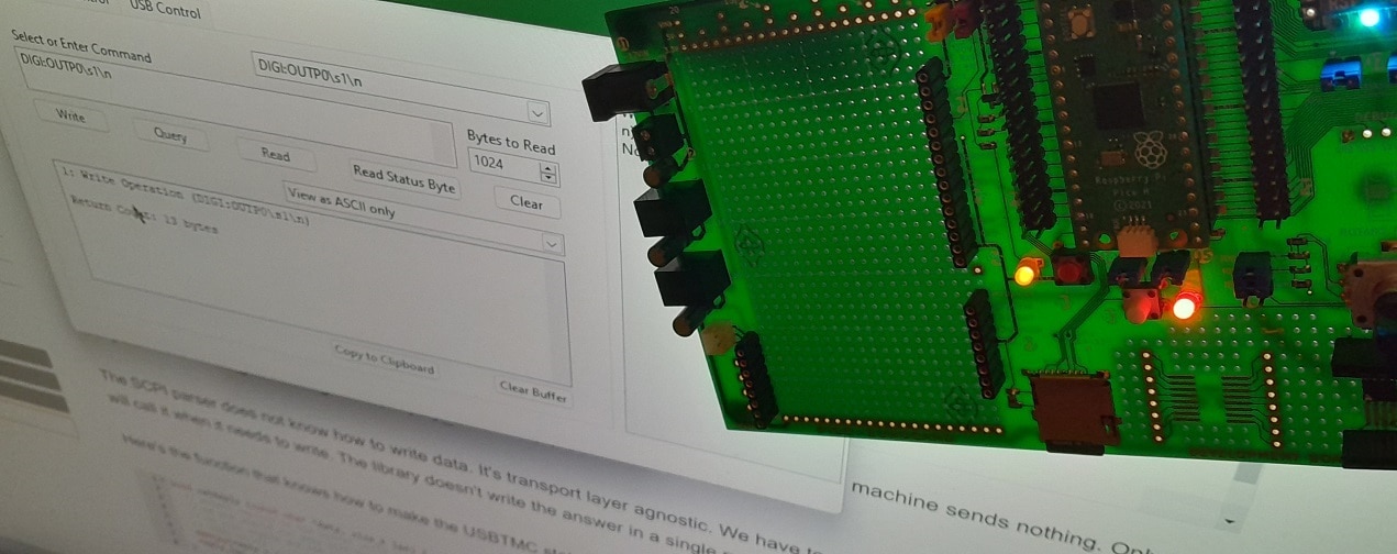
image: the switch mounted on shabaz ' Pico Eurocard. The SCPI command DIGI:OUTP0 {0|1} switches the LED on the card

VSCode project, sources and binaries

Here's the VSCode project archive. It contains the binary uf2 file. You can drag this on your Pico to program it without building from source.
Don't forget to add these two variables to your VSCode user environment:

image

scpi_switch_usbtmc_20230130.zip

link to all posts

  • Sign in to reply
  • Jan Cumps
    Jan Cumps 1 month ago in reply to Jan Cumps

    ... and this is the instrument init code:

    // supported pins
    uint pins[] = {
        /*PICO_DEFAULT_LED_PIN, removed in this project, because the USBTMC code makes good use of it to show USB status
        if you want to use this pin, remove the led_blinking_task() */
        22, 14, 15};
    
    // ...
    
    void initPins() {
        for (uint32_t i = 0; i < pinCount(); i++) {
            gpio_init(pins[i]);
            gpio_set_dir(pins[i], 1);
            gpio_put(pins[i], 0);
        }
    }

    • Cancel
    • Vote Up 0 Vote Down
    • Sign in to reply
    • More
    • Cancel
  • Jan Cumps
    Jan Cumps 1 month ago in reply to Jan Cumps

    In that case, the main file would not include or call he gpio_util functions.

    The SCPI_instrument_init() could look like this:

    // init helper for this instrument
    void scpi_instrument_init() {
        initPins(); // if you prefer no dependency on the gpio_utils in main,
                  // you could move this call into the scpi_instrument_init() body.
                  // like I did here
        
         SCPI_Init(&scpi_context,
                 scpi_commands,
                 &scpi_interface,
                 scpi_units_def,
                 SCPI_IDN1, SCPI_IDN2, SCPI_IDN3, SCPI_IDN4,
                 scpi_input_buffer, SCPI_INPUT_BUFFER_LENGTH,
                 scpi_error_queue_data, SCPI_ERROR_QUEUE_SIZE);
    
    }

    and you could implement the (optional) *RST handler:

    scpi_interface_t scpi_interface = {
        .error = NULL,            // haven't implemented an error logger
        .write = SCPI_Write,
        .control = NULL,        // haven't implemented communication channel control
        .flush = NULL,            // don't need flush for SCI / USB
        .reset = SCPI_Reset,
    };
    
    // ...
    
    
    // ...
    scpi_result_t SCPI_Reset(scpi_t * context) {
        (void) context;
        initPins();
        return SCPI_RES_OK;   
    }

    • Cancel
    • Vote Up 0 Vote Down
    • Sign in to reply
    • More
    • Cancel
  • Jan Cumps
    Jan Cumps 1 month ago

    If you use this project as starting point, part 2:

    The main file does not use (or know) the instrument api in the source/gpio folder. Except for the initialisation function.
    That function prepares the hardware used in the instrument - in this case: sets the gpios to out and low.

    Putting this initialisation call in the main file was a design decision, not random, but maybe not the best.
    I usually make my instruments like this, to have the hardware ready before I initialise the SCPI parser. In particular when I make an instrument with a screen / buttons in parallel with the SCPI engine, this makes sense. I make the user interface call the instrument functions directly. I don't make them call the SCPI parser. 

    In this particular case, where I made an instrument that's only controllable via SCPI, it makes sense to do the initialisation in the scpi_instrument_init() body.
    That would give the advantage that the USBTMC core does not have to know *anything* about what SCPI commands are supported or what the instrument does. You could reuse the code for any instrument.
    In particular, because that same initialisation code could (should?) also be used in the *RST handler ...

    • Cancel
    • Vote Up 0 Vote Down
    • Sign in to reply
    • More
    • Cancel
  • Jan Cumps
    Jan Cumps 1 month ago

    If you use this project as starting point, I tried to keep the code modular:

    there's only two files that knows the instrument-specific scpi commands. Both are located in source\scpi:
    scpi.h has the *IDN? reply settings.
    scpi.c has the supported commands, and what instrument code they should call.

    In my case, there is only one custom command that the device supports:

        {.pattern = "DIGItal:OUTPut#", .callback = SCPI_DigitalOutput,},
    Implementation:
    static scpi_result_t SCPI_DigitalOutput(scpi_t * context) {
    
    
      scpi_bool_t param1;
      int32_t numbers[1];
    
      // retrieve the output index
      SCPI_CommandNumbers(context, numbers, 1, 0);
      if (! ((numbers[0] > -1) && (numbers[0] < pinCount()))) {
        SCPI_ErrorPush(context, SCPI_ERROR_INVALID_SUFFIX);
        return SCPI_RES_ERR;
      }
    
      /* read first parameter if present */
      if (!SCPI_ParamBool(context, &param1, TRUE)) {
        return SCPI_RES_ERR;
      }
    
      setPinAt(numbers[0], param1 ? true : false);
    
      return SCPI_RES_OK;
    }

    All instrument code is in source\gpio. Here I wrote the functions that can be called by the parser:

    uint32_t pinCount() {
        return sizeof(pins)/sizeof(pins[0]);
    }
    
    // ...
    
    void setPinAt(uint32_t index, bool on) {
        gpio_put(pins[index], on);
    }

    • Cancel
    • Vote Up 0 Vote Down
    • Sign in to reply
    • More
    • Cancel
  • DAB
    DAB 1 month ago

    Great blog Jan.

    • Cancel
    • Vote Up 0 Vote Down
    • Sign in to reply
    • More
    • Cancel
>
element14 Community

element14 is the first online community specifically for engineers. Connect with your peers and get expert answers to your questions.

  • Members
  • Learn
  • Technologies
  • Challenges & Projects
  • Products
  • Store
  • About Us
  • Feedback & Support
  • FAQs
  • Terms of Use
  • Privacy Policy
  • Legal and Copyright Notices
  • Sitemap
  • Cookies

An Avnet Company © 2023 Premier Farnell Limited. All Rights Reserved.

Premier Farnell Ltd, registered in England and Wales (no 00876412), registered office: Farnell House, Forge Lane, Leeds LS12 2NE.

ICP 备案号 10220084.

Follow element14

  • Facebook
  • Twitter
  • linkedin
  • YouTube