element14 Community
element14 Community
    Register Log In
  • Site
  • Search
  • Log In Register
  • About Us
  • Community Hub
    Community Hub
    • What's New on element14
    • Feedback and Support
    • Benefits of Membership
    • Personal Blogs
    • Members Area
    • Achievement Levels
  • Learn
    Learn
    • Ask an Expert
    • eBooks
    • element14 presents
    • Learning Center
    • Tech Spotlight
    • STEM Academy
    • Webinars, Training and Events
    • Learning Groups
  • Technologies
    Technologies
    • 3D Printing
    • FPGA
    • Industrial Automation
    • Internet of Things
    • Power & Energy
    • Sensors
    • Technology Groups
  • Challenges & Projects
    Challenges & Projects
    • Design Challenges
    • element14 presents Projects
    • Project14
    • Arduino Projects
    • Raspberry Pi Projects
    • Project Groups
  • Products
    Products
    • Arduino
    • Avnet Boards Community
    • Dev Tools
    • Manufacturers
    • Multicomp Pro
    • Product Groups
    • Raspberry Pi
    • RoadTests & Reviews
  • Store
    Store
    • Visit Your Store
    • Choose another store...
      • Europe
      •  Austria (German)
      •  Belgium (Dutch, French)
      •  Bulgaria (Bulgarian)
      •  Czech Republic (Czech)
      •  Denmark (Danish)
      •  Estonia (Estonian)
      •  Finland (Finnish)
      •  France (French)
      •  Germany (German)
      •  Hungary (Hungarian)
      •  Ireland
      •  Israel
      •  Italy (Italian)
      •  Latvia (Latvian)
      •  
      •  Lithuania (Lithuanian)
      •  Netherlands (Dutch)
      •  Norway (Norwegian)
      •  Poland (Polish)
      •  Portugal (Portuguese)
      •  Romania (Romanian)
      •  Russia (Russian)
      •  Slovakia (Slovak)
      •  Slovenia (Slovenian)
      •  Spain (Spanish)
      •  Sweden (Swedish)
      •  Switzerland(German, French)
      •  Turkey (Turkish)
      •  United Kingdom
      • Asia Pacific
      •  Australia
      •  China
      •  Hong Kong
      •  India
      •  Korea (Korean)
      •  Malaysia
      •  New Zealand
      •  Philippines
      •  Singapore
      •  Taiwan
      •  Thailand (Thai)
      • Americas
      •  Brazil (Portuguese)
      •  Canada
      •  Mexico (Spanish)
      •  United States
      Can't find the country/region you're looking for? Visit our export site or find a local distributor.
  • Translate
  • Profile
  • Settings
Raspberry Pi
  • Products
  • More
Raspberry Pi
Blog Working with the Pi: Getting Online, I/O and Command Lines
  • Blog
  • Forum
  • Documents
  • Quiz
  • Events
  • Polls
  • Files
  • Members
  • Mentions
  • Sub-Groups
  • Tags
  • More
  • Cancel
  • New
Join Raspberry Pi to participate - click to join for free!
Featured Articles
Announcing Pi
Technical Specifications
Raspberry Pi FAQs
Win a Pi
GPIO Pinout
Raspberry Pi Wishlist
Comparison Chart
Quiz
  • Share
  • More
  • Cancel
Group Actions
  • Group RSS
  • More
  • Cancel
Engagement
  • Author Author: shabaz
  • Date Created: 7 Jul 2017 2:21 PM Date Created
  • Views 2246 views
  • Likes 11 likes
  • Comments 6 comments
Related
Recommended
  • coding
  • rpibeginner
  • raspberry pi getting started
  • get started with pi
  • rpi
  • sudo_open
  • raspberry_pi_getting_started

Working with the Pi: Getting Online, I/O and Command Lines

shabaz
shabaz
7 Jul 2017

  • Introduction
  • Enabling Wireless (WiFi)
  • Connecting Input/Output (I/O) Devices to the Expansion Header
  • Quick Linux Reference Guide
  • Powering off the Pi


Introduction

This blog post contains some miscellaneous topics that are handy when working with the Pi. It covers how to enable the wireless capability on the Pi, how to get started attaching your own circuits to the Pi, and a command line guide.


Use this blog post as a quick reference to do these ‘things’:


  • Enabling Wireless (WiFi) connections
  • Connecting Input/Output devices to the Expansion Header
  • Quick Linux Reference Guide
  • Powering off the Pi


Enabling Wireless (WiFi)

The Pi has an Ethernet connection but the recent Pi 3 also has built-in wireless capability. If desired, the wireless can be enabled and the Pi can be disconnected from the Ethernet.


There are several ways to enable and configure the wireless. If you’re using the graphical user interface then the easiest way is to go to the top-right of the screen and click on the wireless connections icon and then click on your wireless network identifier (SSID).

image


If you’re using the command line then the procedure is to edit an existing file (as root user) called wpa_supplicant.conf in the /etc/wpa_supplicant folder on the Pi, and at the end of the file add some lines to it such that the entire file looks like this:


ctrl_interface=DIR=/var/run/wpa_supplicant GROUP=netdev
update_config=1
country=GB


network={
        ssid="wifi1"
        psk="bobbobbob"
        key_mgmt=WPA-PSK
}


Change the content wifi1 within the speech-marks to be the SSID for your wireless network, and change bobbobbob to be the password for your network. Save the file, then (still as root user) type:

wpa_cli reconfigure


Wait a few seconds, then type

ifconfig wlan0 | grep “inet”


If everything went well and the wireless connection was successful then the wireless interface IP address for the Pi will be displayed, and you will be able to connect to it using this address if preferred, instead of the wired Ethernet connection (which can be now unplugged). If you don't see it, try typing reboot and then seeing if the wireless connection comes alive.


Connecting Input/Output (I/O) Devices to the Expansion Header

The Pi has a dual-in-line (DIL) pin header that can be used for connecting up external devices. When creating projects with the Pi one isn’t constrained to sound and video. Attached external hardware can be controlled and monitored too and the expansion header (also known as the GPIO or general purpose I/O connector) provides one way to do that.


This blog post isn’t going to go into much hardware detail, except to suggest that a small amount of hardware is useful to be available to attach to the Pi to experiment in this area. It can be as basic as a single LED and a single push-button switch. An LED could be used to simulate a motor for example; when the LED is lit then the motor may turn.


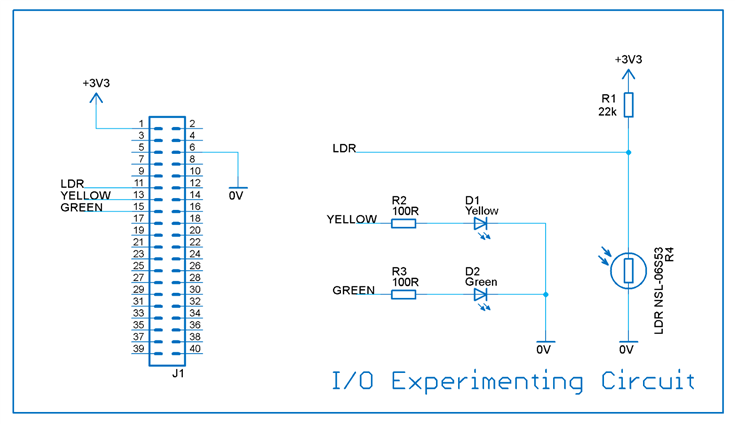
The photo here shows an example setup that could be useful for testing things without needing expensive hardware, high power motors and so on. Here three devices are connected to the Pi; one input device which is a light dependent resistor (LDR), and two output devices which are green and yellow LEDs.

image


It is possible to write some simple code that will turn on the LEDs when the light dependent resistor determines that it is dark. It could be a simulation of an automatic light outside a building.

image


If you want to build the circuit the parts required are:

Light dependent resistorLight dependent resistor

Yellow LEDYellow LED

Green LEDGreen LED

22k Resistor22k Resistor

100R Resistor100R Resistor (two required)

Male-Female Jumper WiresMale-Female Jumper Wires

BreadboardBreadboard


The LEDs need correct orientation; the cathode (C) is always the wire closest to the flattened side of round 5mm LEDs, and is almost always the shorter wire if the wires are of different length. There is no harm if the LED is accidentally reversed in this circuit, the LED just won't light up until it is correctly fitted.

image


A newcomer to a country might just understand a few words of the language and they can still sufficiently understand what someone means.

In a similar vein, there is no need to precisely know how to code in order for even a beginner to be able to mostly follow this computer program:

/******************************************
 * iotest
 * revision 1 shabaz June 2017
 * Header pin 13 is GPIO27 and is connected to a yellow LED
 * Header pin 15 is GPIO22 and is connected to a green LED
 * Header pin 11 is GPIO17 and is connected to a light dependent resistor
 ******************************************/


// includes
#include  <stdio.h>
#include  <wiringPi.h>


// definitions
#define YELLOW_PIN 27
#define GREEN_PIN  22
#define LIGHT_PIN 17


#define FOREVER 1
#define BRIGHT 0
#define DIM 1
#define LED_ON 1
#define LED_OFF 0


/******************************************
 * main program
 ******************************************/
int
main(void)
{
  // define the inputs and outputs
  wiringPiSetupGpio();
  pinMode(LIGHT_PIN, INPUT);
  pinMode(YELLOW_PIN, OUTPUT);
  pinMode(GREEN_PIN, OUTPUT);


  while(FOREVER) // do everything here in loop forever
  {
    if (digitalRead(LIGHT_PIN)==BRIGHT) // is it bright?
    {
      digitalWrite(YELLOW_PIN, LED_OFF); // turn the lights off
      digitalWrite(GREEN_PIN, LED_OFF);
    }
    else // otherwise it must be dark..
    {
      digitalWrite(YELLOW_PIN, LED_ON); // turn the lights on
      digitalWrite(GREEN_PIN, LED_ON);
    }
    delay(100); // wait 100milliseconds and then loop back
  }


  // the next line never executes
  return(0); // warning on this line is ok
}


Some of the lines of the computer program might not make much sense to a complete beginner but by the definitions section (from line 16) it becomes clear that this is a bit like algebra, assigning numbers to characters or names. Then it can be seen that the code is declaring some of these names to be outputs, and one of them to be an input.


The next bit (from row 43) looks a lot like a flow chart with diamond-shaped decision block, where the code is instructing the computer to check if the external hardware connected to the input pin is indicating a bright situation or a dim situation and set the lights (LEDs) on or off accordingly.


More detail and more interesting stuff is the subject for a different blog post, but in the meanwhile the program can be executed by doing the following steps:


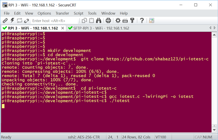
Firstly save the code to a file on the Pi, called (say) iotest.c - a quick way to do this rather than copy-paste is to just grab the code from an online repository where the code has been placed already.


The steps in the screenshot below create a folder called development, and then inside that folder the file from the repository is copied across into a sub-folder called pi-iotest-c. Then inside that folder the program called gcc is executed. It converts the human-readable code into instructions that the computer understands natively. The final line runs the program. Placing the hand over the sensor will make the LEDs light up. To quit the program at any time, press Ctrl-C (i.e. hold down the ctrl button and then press C while ctrl is still held down).

image


Quick Linux Reference Guide

Linux has lots of useful commands, some of the most useful ones are listed here as a 1-page reference. For a beginner it could be useful to print this out and keep it handy, or bookmark this web page. It is also available as a PDF attached to this blog post.

image

image


Powering off the Pi

One important thing to bear in mind is that the power supply shouldn’t be disconnected prior to doing a controlled shutdown of the Linux operating system. There is a menu option when using the graphical interface to perform a controlled shutdown. If you’re using the command prompt then as root user just type poweroff and this will perform the controlled shutdown.


  • Sign in to reply

Top Comments

  • shabaz
    shabaz over 7 years ago +4
    Heads-up for anyone using scripts that parse the ifconfig command output; looks like in recent images, the format has changed, from: wlan0 Link encap:Ethernet HWaddr xx:xx:xx:xx:xx:xx inet addr:192.168…
  • DAB
    DAB over 8 years ago +2
    Hi Shabaz, I have been wanting to play with the new RPI 3 with I/O, but have not had the time. Now that I see how it can be easily done, I will have to make some time. Thanks DAB
  • shabaz
    shabaz over 7 years ago in reply to purchasemail +2
    Hi, There should be a file in the folder called wpa_supplicant.conf, and that file is the one to be edited - sorry, I should have made that clearer. So, the folder is /etc/wpa_supplicant , and the file…
  • shabaz
    shabaz over 6 years ago in reply to e14phil

    Hi Phil,


    Thanks!

    • Cancel
    • Vote Up 0 Vote Down
    • Sign in to reply
    • More
    • Cancel
  • e14phil
    e14phil over 6 years ago in reply to shabaz

    Shabaz is one of the few people I know in his world who updates previous blogs with up to date code changes.

    I feel this should line you up for a nomination in Sainthood.


    Thank you Shabaz.

    • Cancel
    • Vote Up +2 Vote Down
    • Sign in to reply
    • More
    • Cancel
  • shabaz
    shabaz over 7 years ago

    Heads-up for anyone using scripts that parse the ifconfig command output; looks like in recent images, the format has changed, from:


    wlan0     Link encap:Ethernet  HWaddr xx:xx:xx:xx:xx:xx  
              inet addr:192.168.1.100  Bcast:192.168.1.255  Mask:255.255.255.0
              inet6 addr: xxxx::xxxx:xxxx:xxxx:xxxx/64 Scope:Link
              UP BROADCAST RUNNING MULTICAST  MTU:1500  Metric:1
              RX packets:9585324 errors:0 dropped:7539968 overruns:0 frame:0
              TX packets:590584 errors:0 dropped:0 overruns:0 carrier:0
              collisions:0 txqueuelen:1000 
              RX bytes:2813159629 (2.6 GiB)  TX bytes:163158664 (155.6 MiB)


    to:

    wlan0: flags=4163<up,broadcast,running,multicast>  mtu 1500
            inet 192.168.1.101  netmask 255.255.255.0  broadcast 192.168.1.255
            inet6 xxxx::xxxx:xxxx:xxxx:xxxx  prefixlen 64  scopeid 0x20
            ether xx:xx:xx:xx:xx:xx  txqueuelen 1000  (Ethernet)
            RX packets 34  bytes 4219 (4.1 KiB)
            RX errors 0  dropped 2  overruns 0  frame 0
            TX packets 56  bytes 8815 (8.6 KiB)
            TX errors 0  dropped 0 overruns 0  carrier 0  collisions 0

    • Cancel
    • Vote Up +4 Vote Down
    • Sign in to reply
    • More
    • Cancel
  • shabaz
    shabaz over 7 years ago in reply to purchasemail

    Hi,


    There should be a file in the folder called wpa_supplicant.conf, and that file is the one to be edited - sorry, I should have made that clearer.

    So, the folder is /etc/wpa_supplicant, and the file is called wpa_supplicant.conf .

    The file should already exist in that folder, so it is a file edit operation, not a file create operation.


    EDIT 8th May 2018: Now added to the main text in the blog post.

    • Cancel
    • Vote Up +2 Vote Down
    • Sign in to reply
    • More
    • Cancel
  • purchasemail
    purchasemail over 7 years ago

    To enable WiFi using a command line, we are told "the procedure is to edit a file (as root user) in the /etc/wpa_supplicant folder."

    .

    Once root edits (creates?) that file, what should the file be named upon saving it?

    • Cancel
    • Vote Up 0 Vote Down
    • Sign in to reply
    • More
    • Cancel
>
element14 Community

element14 is the first online community specifically for engineers. Connect with your peers and get expert answers to your questions.

  • Members
  • Learn
  • Technologies
  • Challenges & Projects
  • Products
  • Store
  • About Us
  • Feedback & Support
  • FAQs
  • Terms of Use
  • Privacy Policy
  • Legal and Copyright Notices
  • Sitemap
  • Cookies

An Avnet Company © 2025 Premier Farnell Limited. All Rights Reserved.

Premier Farnell Ltd, registered in England and Wales (no 00876412), registered office: Farnell House, Forge Lane, Leeds LS12 2NE.

ICP 备案号 10220084.

Follow element14

  • X
  • Facebook
  • linkedin
  • YouTube