element14 Community
element14 Community
    Register Log In
  • Site
  • Search
  • Log In Register
  • Community Hub
    Community Hub
    • What's New on element14
    • Feedback and Support
    • Benefits of Membership
    • Personal Blogs
    • Members Area
    • Achievement Levels
  • Learn
    Learn
    • Ask an Expert
    • eBooks
    • element14 presents
    • Learning Center
    • Tech Spotlight
    • STEM Academy
    • Webinars, Training and Events
    • Learning Groups
  • Technologies
    Technologies
    • 3D Printing
    • FPGA
    • Industrial Automation
    • Internet of Things
    • Power & Energy
    • Sensors
    • Technology Groups
  • Challenges & Projects
    Challenges & Projects
    • Design Challenges
    • element14 presents Projects
    • Project14
    • Arduino Projects
    • Raspberry Pi Projects
    • Project Groups
  • Products
    Products
    • Arduino
    • Avnet & Tria Boards Community
    • Dev Tools
    • Manufacturers
    • Multicomp Pro
    • Product Groups
    • Raspberry Pi
    • RoadTests & Reviews
  • About Us
    About the element14 Community
  • Store
    Store
    • Visit Your Store
    • Choose another store...
      • Europe
      •  Austria (German)
      •  Belgium (Dutch, French)
      •  Bulgaria (Bulgarian)
      •  Czech Republic (Czech)
      •  Denmark (Danish)
      •  Estonia (Estonian)
      •  Finland (Finnish)
      •  France (French)
      •  Germany (German)
      •  Hungary (Hungarian)
      •  Ireland
      •  Israel
      •  Italy (Italian)
      •  Latvia (Latvian)
      •  
      •  Lithuania (Lithuanian)
      •  Netherlands (Dutch)
      •  Norway (Norwegian)
      •  Poland (Polish)
      •  Portugal (Portuguese)
      •  Romania (Romanian)
      •  Russia (Russian)
      •  Slovakia (Slovak)
      •  Slovenia (Slovenian)
      •  Spain (Spanish)
      •  Sweden (Swedish)
      •  Switzerland(German, French)
      •  Turkey (Turkish)
      •  United Kingdom
      • Asia Pacific
      •  Australia
      •  China
      •  Hong Kong
      •  India
      •  Japan
      •  Korea (Korean)
      •  Malaysia
      •  New Zealand
      •  Philippines
      •  Singapore
      •  Taiwan
      •  Thailand (Thai)
      •  Vietnam
      • Americas
      •  Brazil (Portuguese)
      •  Canada
      •  Mexico (Spanish)
      •  United States
      Can't find the country/region you're looking for? Visit our export site or find a local distributor.
  • Translate
  • Profile
  • Settings
Raspberry Pi
  • Products
  • More
Raspberry Pi
Raspberry Pi Forum Raspberry Pi - Hardware Flaws and Fixups?
  • Blog
  • Forum
  • Documents
  • Quiz
  • Events
  • Polls
  • Files
  • Members
  • Mentions
  • Sub-Groups
  • Tags
  • More
  • Cancel
  • New
Join Raspberry Pi to participate - click to join for free!
Featured Articles
Announcing Pi
Technical Specifications
Raspberry Pi FAQs
Win a Pi
Raspberry Pi Wishlist
Actions
  • Share
  • More
  • Cancel
Forum Thread Details
  • Replies 188 replies
  • Subscribers 717 subscribers
  • Views 22834 views
  • Users 0 members are here
  • flaws
  • hardware
  • single_board_computer
  • single_board_computers
  • raspberry_pi
  • Design
  • fixups
Related

Raspberry Pi - Hardware Flaws and Fixups?

e14 Contributor
e14 Contributor over 14 years ago

Several people have commented on the hardware design of the Raspberry Pi.  Some are buried in other topics so please post your comments here.  I'll try my best to answer questions about the design decisions we made.  The Raspberry Pi is not perfect, never will be.  I've always found that perfect designs have a habit of never getting built, engineers are always a bit guilty of that, but I had Eben phoning/emailing me every day wanting to know when it would be finished.  Also, one persons perfection is another persons nightmare.


e14 is the home for engineers so please contribute to make Raspberry Pi better.


Thanks


Pete

  • Sign in to reply
  • Cancel
Parents
  • morgaine
    morgaine over 14 years ago

    Now that people have actually started receiving the boards so the design in final, is the schematic close to being posted?  I looked around again in various likely places just now, but haven't spotted it yet.

    • Cancel
    • Vote Up 0 Vote Down
    • Sign in to reply
    • Cancel
  • e14 Contributor
    e14 Contributor over 14 years ago in reply to morgaine

    actually, the design may not be quite final yet.  Liz said: "Happily, we’ve found it doesn’t need a shielded enclosure to reach Class B, although it will require a (very minimal) redesign." http://www.raspberrypi.org/archives/978, page 3, April 10, 2012 at 7:04 pm.


    It hasn't been announced when such a change might be implemented, but probably better sooner rather than later, given the large production runs planned, perhaps along with a change to fix the SD card voltage issue.

    • Cancel
    • Vote Up 0 Vote Down
    • Sign in to reply
    • Cancel
  • e14 Contributor
    e14 Contributor over 14 years ago in reply to rew

    I power cycle mine a lot too, and I really wouldn't want to put all that strain on the Pi's power connector either.  I always disconnect the power further down the line.


    Pete, I guess the schematics would tell me this, but do you know if the Pi supports the type of high current connections that Ipod/Ipad do?  i.e. a resistive connection to the D+ and D- pins?  If so, there might not be so much of a voltage drop if we have current going through all four wire (albeit smaller on the D- and D+ wires).

    • Cancel
    • Vote Up 0 Vote Down
    • Sign in to reply
    • Cancel
  • rew
    rew over 14 years ago in reply to e14 Contributor

    Gizmo,

    Those voltages on D+ and D- are not power-carrying.
    Apple wanted to make a powersupply that provided 1A of charging current, but didn't want to be breaking any 500mA standard-USB power-sources. So they decided that 2.0V on D+ and 2.7V on D- will indicate that this is a 1A capable apple charger.


    This is an easy and cheap way to identify the charger. It's just identification.


    The D+ and D- lines on the Micro USB connector are not connected to anything on the RPI.


    -------------------

    Pete, Not sure if you've heard about this, but some people are a bit disappointed that I2S has been dropped. So those are planning on using those strapped pins as access points for the I2S hardware on the SOC.


    If another "board revision" possibility presents itself, that might lead to less problems for those people.


    I was thinking about: The GPU already knows its serial number/MAC address. So could that be used? You guys have 1M mac addresses, right? So if you reserve the top two bits for board revision, you're leaving some 150k mac addresses unused if the current "batch" of 100k boards are rev 0, and the next will be rev 1.


    Or if that sounds wasteful, the mechanism for "personalizing" the SOC that is used for the MAC address can also be used for passing BOARDREV=XXX on the kernel commandline.


    On the other hand, that would require a ROM firmware upgrade to the SOC, right? Is that really ROM? Flash? OTP?

    • Cancel
    • Vote Up 0 Vote Down
    • Sign in to reply
    • Cancel
  • jamodio
    jamodio over 14 years ago in reply to e14 Contributor

    Thanks for the update Pete. Can you provide some detail about what changes are required besides the HDMI configuration in firmware ?


    Do these changes require a pcb layout redesign ? (Perhaps your opportunity to move that eletrolytic)


    Also, does anybody has any piece of concrete information about how many boards have been actually manufactured and shipped out from the assembly house in China?


    Thanks & Regards

    • Cancel
    • Vote Up 0 Vote Down
    • Sign in to reply
    • Cancel
  • e14 Contributor
    e14 Contributor over 14 years ago in reply to rew

    All


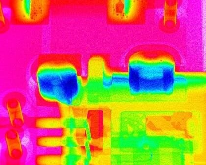
    As a follow up to my previous post here is an X-Ray of the Micro USB.


    image

    Sorry about the funky colour scheme but it hard to pick out the tabs from a lump of solder (lead free) around them (blue in blue).  You should be able to see that the tabs are present and will resist the lateral force applied.  They are not as tall as the thickness of the board as they are primarily used on very thin laminate (0.6mm) and we are at 1.4mm.  I should also mention that we are looking from the back through the PCB.  You can also just see below the tabs, the green area with yellow flecks; that is the two solder pads under the front of the connector, and they seem to be reasonably well soldered.  The voiding (yellow flecks) are normal some better than others.  The orange tubes to the left are vias in the PCB.


    I'm sure if we get any failures of this component I'll be the first to know, because you guys will tell me. image


    I think I'll go an chase some of these posts on power issues relating to duff cables and 'suspected' duff polyfuse parts.  Let you know what I find.


    Pete

    • Cancel
    • Vote Up 0 Vote Down
    • Sign in to reply
    • Cancel
  • e14 Contributor
    e14 Contributor over 14 years ago in reply to e14 Contributor

    Thanks for the microUSB x-ray, very informative! Will look forward to more updates. And meanwhile, this is a cautionary tale:

    http://www.raspberrypi.org/forum/general-discussion/close-call-nearly-bricked-my-rpi#p66238

    • Cancel
    • Vote Up 0 Vote Down
    • Sign in to reply
    • Cancel
  • rew
    rew over 14 years ago in reply to e14 Contributor

    Hi Pete,


    If you're interested, I would think that people who are having troubles are using a power cable or power supply that isn't good enough.

    You must be aware that I and others have measured cables at 3-5 Ohms. That is surely not going to work out well.


    I haven't measured the average current yet, but it could very well be about 0.3A. With a 1 Ohm cable and a 5.1V powersupply that would lead to the 4.8V that someone measured with a multimeter.


    However a burst of 0.7A will then deplete the 220uF in under half a millisecond. (I'm assuming a 0.7V dropout for the 3.3V regulator). That's way too fast to measure with a multimeter. And it's way long enough to brown-out the CPU and/or LAN chip.

    • Cancel
    • Vote Up 0 Vote Down
    • Sign in to reply
    • Cancel
  • e14 Contributor
    e14 Contributor over 14 years ago in reply to rew

    Roger & All


    I'm seeing a few issues relating to this 'brownout' problem.  I've got someone looking at this with fast scope and a selection of cables / PSU's to try to bottom this.  We have not seen this problem in our test set but that is the joy of putting something in the field.


    I'm also trying to get a handle on the population of users that have a problem with this.  Interestingly in one of the tests we did is to run the board w/o the 220uF present and it still worked without problems - so you could be onto something.


    Thanks for the input.


    Pete

    • Cancel
    • Vote Up 0 Vote Down
    • Sign in to reply
    • Cancel
  • e14 Contributor
    e14 Contributor over 14 years ago in reply to rew

    Roger you wrote: "However next in line is my I2C interface. This too is labeled on the GPIO port as: I2C SDA, I2C SCL, and I'll have to guess which of the several I2C interfaces is connected to the GPIO pins"

    The wiki says the I2C are SDA0 SCL0 !

    Are planning on doing an I2C driver?

    I have a batch of Real Time Clock modules that I'd to love to start selling but would like to get them tested on an R-Pi first!


    Or is anyone else with an R-Pi /getting in the next batch, interested in writing an I2C driver? If yes please email me: chris@cjemicros.co.uk

    I'm told that the Linux sources have a driver for the DS1338 that I've used! (there is also support in the RISC OS sources which is how we have tested our design)

    • Cancel
    • Vote Up 0 Vote Down
    • Sign in to reply
    • Cancel
  • rew
    rew over 14 years ago in reply to e14 Contributor

    Hi Chris,

    I've gotten I2C working now from the commandline "bitibanging" utility. I was just browsing around on the forum to find a place where I can post a link to the software. :-)

    Which reminds me: I don't have I2C read implemented yet....[time passes] .... OK. Done! :-)


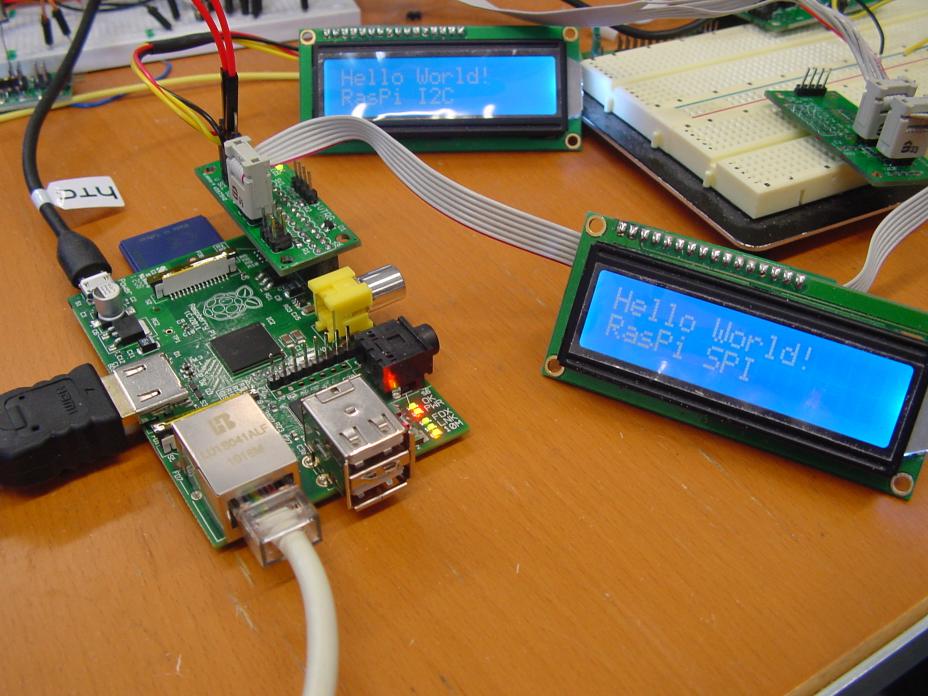
    Here are the commandline utilities to control GPIO, SPI and I2C.

    http://www.bitwizard.nl/software/gpio_spi_i2c_20120419.tgz

    Some sample scripts are included to make it easy to work with my I2c and SPI boards.


    http://prive.bitwizard.nl/dsc04617_small.jpg


    I'll start looking into writing the I2C and SPI kernel drivers shortly.


    It could very well be that I decide that what I want from a kernel driver is not what the standard I2C and SPI kernel drivers do. I want to be able to easily, from userspace, interact with the devices on the bus. Eventually it should be something like:

    echo 1 > /dev/motor

    and the motor starts turning. :-)


    OT: Chris, your name sounds familiar. Were you involved with Linux in the early years? Google shows that there is an actor with your name too. (or is that you?) :-)

    • Cancel
    • Vote Up +1 Vote Down
    • Sign in to reply
    • Cancel
  • e14 Contributor
    e14 Contributor over 14 years ago in reply to rew

    Great work Roger! I've emailed you via the bitwizard site.

    There are a few Chris Evans's about. I'm new to Linux!

    • Cancel
    • Vote Up 0 Vote Down
    • Sign in to reply
    • Cancel
Reply
  • e14 Contributor
    e14 Contributor over 14 years ago in reply to rew

    Great work Roger! I've emailed you via the bitwizard site.

    There are a few Chris Evans's about. I'm new to Linux!

    • Cancel
    • Vote Up 0 Vote Down
    • Sign in to reply
    • Cancel
Children
No Data
element14 Community

element14 is the first online community specifically for engineers. Connect with your peers and get expert answers to your questions.

  • Members
  • Learn
  • Technologies
  • Challenges & Projects
  • Products
  • Store
  • About Us
  • Feedback & Support
  • FAQs
  • Terms of Use
  • Privacy Policy
  • Legal and Copyright Notices
  • Sitemap
  • Cookies

An Avnet Company © 2026 Premier Farnell Limited. All Rights Reserved.

Premier Farnell Ltd, registered in England and Wales (no 00876412), registered office: Farnell House, Forge Lane, Leeds LS12 2NE.

Follow element14

  • X
  • Facebook
  • linkedin
  • YouTube