element14 Community
element14 Community
    Register Log In
  • Site
  • Search
  • Log In Register
  • Community Hub
    Community Hub
    • What's New on element14
    • Feedback and Support
    • Benefits of Membership
    • Personal Blogs
    • Members Area
    • Achievement Levels
  • Learn
    Learn
    • Ask an Expert
    • eBooks
    • element14 presents
    • Learning Center
    • Tech Spotlight
    • STEM Academy
    • Webinars, Training and Events
    • Learning Groups
  • Technologies
    Technologies
    • 3D Printing
    • FPGA
    • Industrial Automation
    • Internet of Things
    • Power & Energy
    • Sensors
    • Technology Groups
  • Challenges & Projects
    Challenges & Projects
    • Design Challenges
    • element14 presents Projects
    • Project14
    • Arduino Projects
    • Raspberry Pi Projects
    • Project Groups
  • Products
    Products
    • Arduino
    • Avnet Boards Community
    • Dev Tools
    • Manufacturers
    • Multicomp Pro
    • Product Groups
    • Raspberry Pi
    • RoadTests & Reviews
  • Store
    Store
    • Visit Your Store
    • Choose another store...
      • Europe
      •  Austria (German)
      •  Belgium (Dutch, French)
      •  Bulgaria (Bulgarian)
      •  Czech Republic (Czech)
      •  Denmark (Danish)
      •  Estonia (Estonian)
      •  Finland (Finnish)
      •  France (French)
      •  Germany (German)
      •  Hungary (Hungarian)
      •  Ireland
      •  Israel
      •  Italy (Italian)
      •  Latvia (Latvian)
      •  
      •  Lithuania (Lithuanian)
      •  Netherlands (Dutch)
      •  Norway (Norwegian)
      •  Poland (Polish)
      •  Portugal (Portuguese)
      •  Romania (Romanian)
      •  Russia (Russian)
      •  Slovakia (Slovak)
      •  Slovenia (Slovenian)
      •  Spain (Spanish)
      •  Sweden (Swedish)
      •  Switzerland(German, French)
      •  Turkey (Turkish)
      •  United Kingdom
      • Asia Pacific
      •  Australia
      •  China
      •  Hong Kong
      •  India
      •  Korea (Korean)
      •  Malaysia
      •  New Zealand
      •  Philippines
      •  Singapore
      •  Taiwan
      •  Thailand (Thai)
      • Americas
      •  Brazil (Portuguese)
      •  Canada
      •  Mexico (Spanish)
      •  United States
      Can't find the country/region you're looking for? Visit our export site or find a local distributor.
  • Translate
  • Profile
  • Settings
Raspberry Pi
  • Products
  • More
Raspberry Pi
Raspberry Pi Forum Pi Hardware mods
  • Blog
  • Forum
  • Documents
  • Quiz
  • Events
  • Polls
  • Files
  • Members
  • Mentions
  • Sub-Groups
  • Tags
  • More
  • Cancel
  • New
Join Raspberry Pi to participate - click to join for free!
Featured Articles
Announcing Pi
Technical Specifications
Raspberry Pi FAQs
Win a Pi
Raspberry Pi Wishlist
Actions
  • Share
  • More
  • Cancel
Forum Thread Details
  • Replies 10 replies
  • Subscribers 665 subscribers
  • Views 628 views
  • Users 0 members are here
  • raspberry_pi
Related

Pi Hardware mods

Former Member
Former Member over 12 years ago

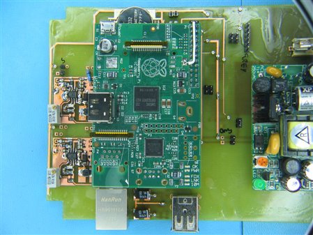
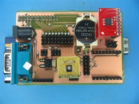
I've been a bit quiet on the R-Pi front for a while, so I thought some of you might enjoy a quick look at what I've been up to.


imageimage

There's some more at https://picasaweb.google.com/selsinork/RaspberryPiModifications


So any guesses what I've been building ?

  • Sign in to reply
  • Cancel
  • johnbeetem
    johnbeetem over 12 years ago

    This isn't really a guess, because I've been watching your comments for a long time, but it's nice to see the PCBs.  Top board looks like you've replaced the now-missing 3.3V and 1.8V linear regulators with switchers.   How's the 5V power consumption?  Bottom board looks like RTC and RS-232 (and/or RS-485), along with a decent power jack.


    How do you make your PC boards?  Top one looks like flexible PCB laminated onto a solid board.

    • Cancel
    • Vote Up 0 Vote Down
    • Sign in to reply
    • Cancel
  • Former Member
    Former Member over 12 years ago in reply to johnbeetem

    pcbs are just standard uv exposure then etched, what makes that top one look rather odd is that I tend to coat them with fluxflux which I find dries hard enough to give the board a reasonable amount of protection from oxidisation and the like while making soldering much easier. Something didn't go quite right with that board though, the flux is rather patchy, some areas are bare and others have very thick deposits.


    the switchers are based on the TPS54231 that jamodio suggested on here way back this time last year. Simplistic measurements show them to be just under 90% efficient and the overall temperature of the Pi has dropped noticeably.  As you can probably guess I'm intending to adjust the 1.8v up just enough that the lan9512 isn't the source of 1.8v for everything else.


    Haven't looked at 5v consumption yet, was going to do that the other day and then realised that I didn't leave myself a convenient place to tap into for a current measurement. So I'll need to remove the main psu from the board to get some measurements. Prototypes are such fun.. there's always something you forgot that will require version 2.0 image

    Anyway, after some initial buglets (flux makes it easy to put shorts on the board too!) it's running with thisthis small 4W supply quite happily instead of the much larger one in the photo. I put footprints on the board for three different psu's, hoping the small one would be ok, but giving myself an upgrade path to a 10W or 15W supply if necessary. A short behind a cap at the usb power switch led to some initial odd behaviour and a change to the bigger supply, which promptly fried the cap and let me find the short!


    Both boards have essentially the same MCP79410 RTC, which with a little platform data means the clock gets automagically set on boot by the kernel, no messing with modules or hwclock here.


    Top board also has a proper usb power switch, sadly that'll only work for a v1 Pi as the easy access to the connections on the lan9512 have been removed on the v2. You could do it on a v2 with some fiddly soldering direct to the pins of the lan9512, but I'm not sure if I can be bothered with that.


    bottom board has the sensible power connector, rs232, pi-face compatible mcp23s17 gpio expander, RTC, temperature sensor and connection points for some sparkfun breakouts including humiity and barometric pressure sensors, then level shifting for some 5v I2C stuff to be connected.


    In the bigger picture, this was one of the goals:

    root@rpi2:~# ntpq -p

         remote           refid      st t when poll reach   delay   offset  jitter

    ==============================================================================

    oGPS_NMEA(0)     .GPS.            0 l    -   16  377    0.000   -0.001   0.001

    *10.44.0.1       193.62.22.82     2 u   37   64  377    0.414   -3.592   0.036

    +10.44.0.5       194.238.48.2     3 u   44   64  377    0.589   -3.509   0.044


    Next challenge is getting it into a case...

    • Cancel
    • Vote Up +1 Vote Down
    • Sign in to reply
    • Cancel
  • fustini
    fustini over 12 years ago

    Thanks for sharing.  I'm impressed by your gallery, and it's very interesting.  I've not seen such extensive modifications before.

    • Cancel
    • Vote Up 0 Vote Down
    • Sign in to reply
    • Cancel
  • Former Member
    Former Member over 12 years ago in reply to fustini

    I don't like to do things by halfs image


    seriously though, I was after something that I can get to 'appliance' level, i.e plug it into power and network and it just works.. and needs to sit in it's box and keep working indefinately. So a lot of stuff simply isn't required, having a go at fixing some of the problems along the way comes with the territory.


    The Pi makes a surprisingly neat little plug-in module once you start down the path I've taken here.  More to come and I'll try to get a blog post up for these two soon.

    • Cancel
    • Vote Up +1 Vote Down
    • Sign in to reply
    • Cancel
  • Former Member
    Former Member over 12 years ago in reply to Former Member

    Those look really good, selsinork image


    Just a small point, though - I really wouldn't recommend coating your boards in flux.  Flux is intended to remove oxidisation at the point of soldering, not to work as a permanent barrier.  You run the risk of having the chemicals start to eat away at components once they get hot!


    For a proper comformal coating, you'd be better off using something like Humiseal (Farnell sells a spray called PPC121 that would also do the job).

    • Cancel
    • Vote Up 0 Vote Down
    • Sign in to reply
    • Cancel
  • Former Member
    Former Member over 12 years ago in reply to Former Member

    Jevan Bryant wrote:


    Just a small point, though - I really wouldn't recommend coating your boards in flux.  Flux is intended to remove oxidisation at the point of soldering, not to work as a permanent barrier.  You run the risk of having the chemicals start to eat away at components once they get hot!


    It certainly wasn't my intention to start a debate on this, but anyway...  First, I understand where you're comming from, and I'd not disagree that it's not designed as a permanent barrier. However my risk here is small on tiny batches of prototype boards, so certainly acceptable to me.


    But I also believe you have some mis-understandings about current technology in fluxes (although I'm likely out of date too).


    Most any flux you can easily get your hands on in likely the last 15-20 years is very specifically no-clean flux, it's designed to stay on the board and not to be reactive or corrosive even in the face of elevated temperatures. There's a good reason for this and the elecronics industry has invested considerable time, effort and money in the technology.


    The traditional way to clean flux off boards was to use CFC's and when these were banned in the late 1980's the industry looked for alternatives.  Now at this point you have to take into account that electronics is primarily a high volume commercial, for profit, enterprise. So they looked for the cheapest alternative!  It turns out that the cheapest alternative is actually the whole no-clean thing. The activation temperature for the flux is not far short of the point where the solder melts and the components fall off the board anyway (likely higher nowadays with lead-free solder having a higher melting point) so typically higher than the normal operating temperature of common components. Otherwise it's a chemically inert insulator.


    As for the cost aspect ?  Well if you save the time, effort, people & chemicals required for cleaning then there's a tangible benefit that beancounters can see.  There's also other benefits where you have components that can't go through a cleaning process and either need special protection measures or have to be added later by hand, avoiding that can be an additional saving.


    Anyway, feel free not to believe me - I'm sure there's many people who won't. But please at least try to do a little research into the subject yourself, here's a starter http://www.ami.ac.uk/courses/topics/0249_conc/index.html which has quite a nice overview of the problems and some of the solutions.


    Slightly off topic, but does anyone remember their workplace being littered in bright blue 40gallon drums of 'Arklone' ?

    • Cancel
    • Vote Up 0 Vote Down
    • Sign in to reply
    • Cancel
  • Former Member
    Former Member over 12 years ago in reply to Former Member

    selsinork wrote:


    Most any flux you can easily get your hands on in likely the last 15-20 years is very specifically no-clean flux, it's designed to stay on the board and not to be reactive or corrosive even in the face of elevated temperatures. There's a good reason for this and the elecronics industry has invested considerable time, effort and money in the technology.


    'No-clean' flux is designed not to leave harmful residues that need to be cleaned from the board (or at least, to leave fewer harmful residues, which may be acceptable unless you're designing a product to last several decades).  Therefore for industrial methods such as wave soldering and reflow soldering, the excess flux will be washed off by the solder and the flux that is used forming solder joints will be (effectively) used up and leave only the 'no-clean' residues.  In both methods, the chemicals that could cause corrosion are boiled off or otherwise removed.


    What you are doing is coating the entire board in flux, soldering a few joints - which will leave harmless residues (assuming you're using no-clean flux) but, notably, these joints will not be protected against oxidation - and on the rest of the board, you're leaving 'raw' flux, with all the nasty corrosive chemicals that were designed to boil off during soldering.


    So I'm afraid I must turn your accusation back at you and say that I believe you have some misunderstandings about current technology in fluxes! image  Having said that, I'm not going to pretend I'm an expert on the subject... though I certainly wouldn't want to go coating PCBs in flux just to protect against a little oxidation.

    • Cancel
    • Vote Up 0 Vote Down
    • Sign in to reply
    • Cancel
  • Former Member
    Former Member over 12 years ago in reply to Former Member

    Anyway, feel free not to believe me - I'm sure there's many people who won't. But please at least try to do a little research into the subject yourself, here's a starter http://www.ami.ac.uk/courses/topics/0249_conc/index.html which has quite a nice explanation of what makes a flux 'no-clean'.  The key detail is that the residues are safe to leave on the board, not the flux itself.

    • Cancel
    • Vote Up 0 Vote Down
    • Sign in to reply
    • Cancel
  • michaelkellett
    michaelkellett over 12 years ago in reply to Former Member

    For what it's worth I'll add my flux experience:


    No clean flux as used in mass production soldering is OK unless you need low leakage resistance or good environmental resistance. If you will need to conformally coat the boards to get good leakage/hunidity performance then you must clean the flux off first.


    For prototype boards I use Warton Metals Future 315 Low Residue Flux which is nice to use (very low viscosity) but leaves very hygroscopic (water attracting) residue. I always clean the baords using Safewash in ultrasonic, rinse in tap water and three rinses in de-ionised water. A little over the top perhaps but prototypes have enough ways of going wrong without adding any more.


    MK

    • Cancel
    • Vote Up 0 Vote Down
    • Sign in to reply
    • Cancel
  • jamodio
    jamodio over 12 years ago

    Very nice, thanks for sharing !!!


    I like that you took care of the power supplies using the TPS54231, I love those litte switchers and now I'm getting in love with even a smaller one for other application which can handle up to 1.2A, the TPS62080 which has some variants with fixed outputs. But it is a small QFN not really very prototype friendly.


    Since I'm getting involved in some educational efforts I may put together a design for an add on board designed around activities for the kids. I like the one you did with the serial interface, I'd go probably go with the FTDI chip for a serial-USB converter given that most of the laptops/netbooks we'll have no longer have the old COM serial ports. I don't think I'll replace the 3.3V and 1.8V regulators but most probably put something better for the main 5V like I did with the TPS54231 for one of the boards I've.


    I'm really waiting for the Model A to become available in the US, the plan is to have them just with wifi, use VNC from the netbooks and perhaps a 802.15.4 option.


    It is not a great piece of engineering but I recently tested the PiMatrix http://www.youtube.com/watch?v=7hiOmja1a7A it is a good gizmo to teach kids how computers work, binary and hexadecimal numbers, etc. I'll most probably post online some of the ideas using Python and Scratch.


    Cheers

    Jorge

    • Cancel
    • Vote Up 0 Vote Down
    • Sign in to reply
    • Cancel
element14 Community

element14 is the first online community specifically for engineers. Connect with your peers and get expert answers to your questions.

  • Members
  • Learn
  • Technologies
  • Challenges & Projects
  • Products
  • Store
  • About Us
  • Feedback & Support
  • FAQs
  • Terms of Use
  • Privacy Policy
  • Legal and Copyright Notices
  • Sitemap
  • Cookies

An Avnet Company © 2025 Premier Farnell Limited. All Rights Reserved.

Premier Farnell Ltd, registered in England and Wales (no 00876412), registered office: Farnell House, Forge Lane, Leeds LS12 2NE.

ICP 备案号 10220084.

Follow element14

  • X
  • Facebook
  • linkedin
  • YouTube