

I have a raspberry pi and I was wondering if there was a way to make the GPIO pins control a DC motor in both directions.
I came up with a little schematic but I'm sure I did it horribly wrong.
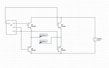
Any suggestions would be greatly appreciated!


I have a raspberry pi and I was wondering if there was a way to make the GPIO pins control a DC motor in both directions.
I came up with a little schematic but I'm sure I did it horribly wrong.
Any suggestions would be greatly appreciated!
