element14 Community
element14 Community
    Register Log In
  • Site
  • Search
  • Log In Register
  • Community Hub
    Community Hub
    • What's New on element14
    • Feedback and Support
    • Benefits of Membership
    • Personal Blogs
    • Members Area
    • Achievement Levels
  • Learn
    Learn
    • Ask an Expert
    • eBooks
    • element14 presents
    • Learning Center
    • Tech Spotlight
    • STEM Academy
    • Webinars, Training and Events
    • Learning Groups
  • Technologies
    Technologies
    • 3D Printing
    • FPGA
    • Industrial Automation
    • Internet of Things
    • Power & Energy
    • Sensors
    • Technology Groups
  • Challenges & Projects
    Challenges & Projects
    • Design Challenges
    • element14 presents Projects
    • Project14
    • Arduino Projects
    • Raspberry Pi Projects
    • Project Groups
  • Products
    Products
    • Arduino
    • Avnet Boards Community
    • Dev Tools
    • Manufacturers
    • Multicomp Pro
    • Product Groups
    • Raspberry Pi
    • RoadTests & Reviews
  • Store
    Store
    • Visit Your Store
    • Choose another store...
      • Europe
      •  Austria (German)
      •  Belgium (Dutch, French)
      •  Bulgaria (Bulgarian)
      •  Czech Republic (Czech)
      •  Denmark (Danish)
      •  Estonia (Estonian)
      •  Finland (Finnish)
      •  France (French)
      •  Germany (German)
      •  Hungary (Hungarian)
      •  Ireland
      •  Israel
      •  Italy (Italian)
      •  Latvia (Latvian)
      •  
      •  Lithuania (Lithuanian)
      •  Netherlands (Dutch)
      •  Norway (Norwegian)
      •  Poland (Polish)
      •  Portugal (Portuguese)
      •  Romania (Romanian)
      •  Russia (Russian)
      •  Slovakia (Slovak)
      •  Slovenia (Slovenian)
      •  Spain (Spanish)
      •  Sweden (Swedish)
      •  Switzerland(German, French)
      •  Turkey (Turkish)
      •  United Kingdom
      • Asia Pacific
      •  Australia
      •  China
      •  Hong Kong
      •  India
      •  Korea (Korean)
      •  Malaysia
      •  New Zealand
      •  Philippines
      •  Singapore
      •  Taiwan
      •  Thailand (Thai)
      • Americas
      •  Brazil (Portuguese)
      •  Canada
      •  Mexico (Spanish)
      •  United States
      Can't find the country/region you're looking for? Visit our export site or find a local distributor.
  • Translate
  • Profile
  • Settings
Raspberry Pi
  • Products
  • More
Raspberry Pi
Raspberry Pi Forum Help with breadboard
  • Blog
  • Forum
  • Documents
  • Quiz
  • Events
  • Polls
  • Files
  • Members
  • Mentions
  • Sub-Groups
  • Tags
  • More
  • Cancel
  • New
Join Raspberry Pi to participate - click to join for free!
Featured Articles
Announcing Pi
Technical Specifications
Raspberry Pi FAQs
Win a Pi
Raspberry Pi Wishlist
Actions
  • Share
  • More
  • Cancel
Forum Thread Details
  • Replies 4 replies
  • Subscribers 666 subscribers
  • Views 516 views
  • Users 0 members are here
  • raspberry_pi
Related

Help with breadboard

Former Member
Former Member over 10 years ago

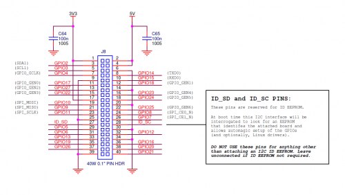
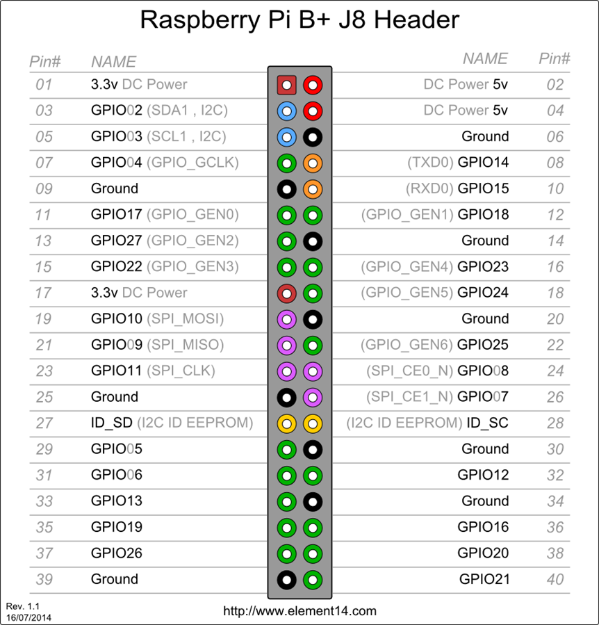
Hello all, I have no clue what I am doing when it comes to using a breadboard and raspberry pi. I found a DIY for reptile enclosure that I am building it is located here: http://www.raspiviv.com/raspberry-pi-vivarium-controller/fans

I am comforable with the code etc, but unsure what to do with the breadboard. I need 2 5V computer fans hooked up to the breadboard which will be automatically activated when humidity hits a certain level. I understand that this is laid out but the examples are chinese to me. Any advice on how to see exactly how the wiring needs to be besides what has been provided? Thanks in advance!

  • Sign in to reply
  • Cancel
  • Former Member
    Former Member over 10 years ago

    forgot to mention, the initial sensor setup is here: http://www.raspiviv.com/raspberry-pi-vivarium-controller/sensors

    so I have to do that first, and then add the fans to the breadboard. I am just confused as to how to do so as I have never worked with a breadboard before. Thank you for any advice!

    • Cancel
    • Vote Up 0 Vote Down
    • Sign in to reply
    • Cancel
  • dtsartsanis
    dtsartsanis over 10 years ago

    You have to transfer your PI GPIO to the breadboard with a cable or a cobbler or wires.

    learn_raspberry_pi_cobbler.jpg?1396790908


    gpio-ribbon-cable-for-raspberry-pi-b.jpg


    raspberry-pi-gpio-ribbon-cable-rainbow-2-800x533.jpg

    I prefer a cobbler because you have the number of the gpios. If u accomplish that then it is very easy to wire them

    As i can see to the tutorial u use 3 sensor.

    1.Black cable of the sensors goes to Pi GPIO GND pin

    2.Red cable of the sensors goes to PI GPIO 3V3 pin

    3,Yellow cable of the sensors goes to PI GPIO02,GPIO03,GPIO04 pins

    Wire the sensors to ground (black - pin 6) 3.3v (red - pin 1) and WiringPi pins 7, 8, 9 (yellow - pins 3, 5, 7)


    You must also find which Pi the tutorial use and what do u have because there maybe some differences to the GPIO. Models B+ and 2 have more pins.

    • Cancel
    • Vote Up +3 Vote Down
    • Sign in to reply
    • Cancel
  • Robert Peter Oakes
    Robert Peter Oakes over 10 years ago

    If you have never done this before I would suggest starting with the basics


    Blinking an LED

    Reading a temperature

    How to drive a relay (To drive the fan as you cant directly from the PI)

    How to run python or C++ on a PI


    Once you have some experience with each then start combining them into a bigger project


    The last thing you want is to subject your dependent reptiles to bad code or wiring image


    Peter

    • Cancel
    • Vote Up +2 Vote Down
    • Sign in to reply
    • Cancel
  • royleith
    royleith over 10 years ago

    The instructions are OK if you know what you are doing. Have a look at Dimitrios' first picture. All of the holes with a red or a blue line by them are connected together vertically as a power bus bar. The author has connected the +5Volt GPIO Pin 2 to one of the +ve (red) bus bars using a jumper lead. The positive lead from the mini blowers is plugged into a spare position on this bus bar. He has not connected the 0Volt Ground Pin 6 to the -ve (blue) bus bar and has chosen to connect it to one of the 5-pin buses described in the next paragraph.


    The breadboard has two halves and each half has a +ve and a -ve bus bar. Each of the five horizontal holes in a row are connected together. The author has connected a jumper lead from GPIO Pins 18 and 22 to two of these 5-pin buses (but you can only see one of them). A 10KΩ resistor is also plugged into each 5 pin bus. The other end is plugged into another horizontal bus and the base connection of the transistor is plugged into the same bus. The transistor collectors are plugged into the adjacent bus which is also connected to the 0V or Ground GPIO Pin 6. The transistor emitters are connected to a third 5-pin bus and so is the negative lead from the mini blower.


    The Raspi sends a low current, +3.3V signal on GPIO Pin 18 or 22 via the 10k resistor to the base of the relevant transistor. This tiny current and voltage is enough to make the transistor conduct from emitter to collector, but not enough to overload the Raspi GPIO pins. Power flows from the Raspi +5V supply at GPIO pin 2 to the +ve of the blower, through the blower to the negative lead and on to the emitter of the transistor. It flows through the transistor to the collector and thence to Ground.


    The Raspi is providing all the 5 Volt power to the mini-blowers. You must make sure to use blowers that only use modest power as anything more will either 'blow' the Pi fuses or lock up the Raspi because of too much voltage drop down the Pi's USB power lead.


    You need to be careful with the GPIO pin numbers. The diagram does not show a complete GPIO header. These should help you out. Pin 1 is marked on the Raspi PCB.imageimage

    • Cancel
    • Vote Up +4 Vote Down
    • Sign in to reply
    • Cancel
element14 Community

element14 is the first online community specifically for engineers. Connect with your peers and get expert answers to your questions.

  • Members
  • Learn
  • Technologies
  • Challenges & Projects
  • Products
  • Store
  • About Us
  • Feedback & Support
  • FAQs
  • Terms of Use
  • Privacy Policy
  • Legal and Copyright Notices
  • Sitemap
  • Cookies

An Avnet Company © 2025 Premier Farnell Limited. All Rights Reserved.

Premier Farnell Ltd, registered in England and Wales (no 00876412), registered office: Farnell House, Forge Lane, Leeds LS12 2NE.

ICP 备案号 10220084.

Follow element14

  • X
  • Facebook
  • linkedin
  • YouTube