element14 Community
element14 Community
    Register Log In
  • Site
  • Search
  • Log In Register
  • About Us
  • Community Hub
    Community Hub
    • What's New on element14
    • Feedback and Support
    • Benefits of Membership
    • Personal Blogs
    • Members Area
    • Achievement Levels
  • Learn
    Learn
    • Ask an Expert
    • eBooks
    • element14 presents
    • Learning Center
    • Tech Spotlight
    • STEM Academy
    • Webinars, Training and Events
    • Learning Groups
  • Technologies
    Technologies
    • 3D Printing
    • FPGA
    • Industrial Automation
    • Internet of Things
    • Power & Energy
    • Sensors
    • Technology Groups
  • Challenges & Projects
    Challenges & Projects
    • Design Challenges
    • element14 presents Projects
    • Project14
    • Arduino Projects
    • Raspberry Pi Projects
    • Project Groups
  • Products
    Products
    • Arduino
    • Avnet Boards Community
    • Dev Tools
    • Manufacturers
    • Multicomp Pro
    • Product Groups
    • Raspberry Pi
    • RoadTests & Reviews
  • Store
    Store
    • Visit Your Store
    • Choose another store...
      • Europe
      •  Austria (German)
      •  Belgium (Dutch, French)
      •  Bulgaria (Bulgarian)
      •  Czech Republic (Czech)
      •  Denmark (Danish)
      •  Estonia (Estonian)
      •  Finland (Finnish)
      •  France (French)
      •  Germany (German)
      •  Hungary (Hungarian)
      •  Ireland
      •  Israel
      •  Italy (Italian)
      •  Latvia (Latvian)
      •  
      •  Lithuania (Lithuanian)
      •  Netherlands (Dutch)
      •  Norway (Norwegian)
      •  Poland (Polish)
      •  Portugal (Portuguese)
      •  Romania (Romanian)
      •  Russia (Russian)
      •  Slovakia (Slovak)
      •  Slovenia (Slovenian)
      •  Spain (Spanish)
      •  Sweden (Swedish)
      •  Switzerland(German, French)
      •  Turkey (Turkish)
      •  United Kingdom
      • Asia Pacific
      •  Australia
      •  China
      •  Hong Kong
      •  India
      •  Korea (Korean)
      •  Malaysia
      •  New Zealand
      •  Philippines
      •  Singapore
      •  Taiwan
      •  Thailand (Thai)
      • Americas
      •  Brazil (Portuguese)
      •  Canada
      •  Mexico (Spanish)
      •  United States
      Can't find the country/region you're looking for? Visit our export site or find a local distributor.
  • Translate
  • Profile
  • Settings
Raspberry Pi
  • Products
  • More
Raspberry Pi
Raspberry Pi Forum PI race condition prevents startup
  • Blog
  • Forum
  • Documents
  • Quiz
  • Events
  • Polls
  • Files
  • Members
  • Mentions
  • Sub-Groups
  • Tags
  • More
  • Cancel
  • New
Join Raspberry Pi to participate - click to join for free!
Featured Articles
Announcing Pi
Technical Specifications
Raspberry Pi FAQs
Win a Pi
Raspberry Pi Wishlist
Actions
  • Share
  • More
  • Cancel
Forum Thread Details
  • State Suggested Answer
  • Replies 22 replies
  • Answers 11 answers
  • Subscribers 664 subscribers
  • Views 3774 views
  • Users 0 members are here
  • raspberry_pi
Related

PI race condition prevents startup

colporteur
colporteur over 6 years ago

G'Day,

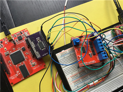
I have a Pi 3B+ connected to an interface board developed in this RoadTest Review New Year's Grab Bag RoadTest - Review The interface board has its own 3VDC and 5VDC power supplies. If the interface board is powered up before the Pi, the Pi will refuse to start. It starts but I never get network capabilities.  If the Pi is powered up first, bothe the Pi and the interface board operate as designed.


The caveat is, I have one Pi that works without the needed the power sequence and another that will only function if the power is applied in the sequence. I have another half dozen Pi's I can try to see what happens but before that I thought it be nice to white board the issue.


I am "napkin developing" a strategy for investigating and was hoping for some community insight and experiences. COmmentary in the past has enabled me to solve other problems I have posted relatively fast.  I'm thinking this might be a power issue. The Pi power supply is being loaded by the interface board on power up causing it to fail boot. How could I see this on the Pi?  I'm in the infancy of testing at the moment so what to look for and where to look would be of value.


Mother's Day supper is starting so I will have to sign-off. I'm hoping I provided sufficient information to start the discussion.

Sean

  • Sign in to reply
  • Cancel
Parents
  • colporteur
    0 colporteur over 6 years ago

    G'Day,

    I thought I would give this discussion the tag of being answered. I found this information recently and thought I would share it and get your feedback.


    I find my mind is like a fridge with post-it notes attached. The notes contain details for unanswered questions. I hope in my daily travels I might run across something that might answer the nagging post-it question, so I can remove it from my mind and make room for other questions that seem to follow.


    image


    Attached is a drawing I found for bi-directional level shifter. My Pi project is still experiencing the race condition. I moved into vacation mode (if such a thing exist for us retired folks) and didn't get back to completing some additional testing to isolate the problem. I am curious if the circuit shown on the bottom would eliminate my problem. The Pi 3.3VDC would provide the low voltage and the high voltage would be externally sourced.


    I am two months away from being able to do any testing. This seems like a solution to me. Care to comment.


    Sean

    • Cancel
    • Vote Up +2 Vote Down
    • Sign in to reply
    • Verify Answer
    • Reject Answer
    • Cancel
  • shabaz
    0 shabaz over 6 years ago in reply to colporteur

    Hi Sean,


    Such a design probably needs testing, and at different voltage scenarios. It's hard to tell, because it's a non-standard layout and there's a lot of combinations to go through. Also I couldn't tell what VDD3 is connected to. I'm wary about such designs, because something could get missed. For example, in that lower design, there's no current-limiting resistor at the gate, it just goes directly to the supply rail. (often a small resistor at the gate terminal is helpful, to protect the gate (e.g. at power-on if whatever supply is connected at the VDD1 or VDD2 end has low impedance). I can see how it might work with 3 MOSFETs per line, by appending a standard layout dual back-to-back MOSFETs to first earlier level shifter circuit, but that lower circuit is trying to do it all in 2 MOSFETs, I guess it is feasible, but just not a scheme I've encountered before, and so would need testing (just a personal opinion.. others may be more familiar with that circuit and what to expect).


    Also, just to check, is it essential that this design should be self-aware about logic direction, and handle the power sequencing requirement? It gives me warning signals, because it makes the design more temperamental I feel, since now the logic levels are more vague compared to using logic ICs and a fixed direction. In other words one direction logic level translators, restricting the design to have certain connections input-only, and certain connections output-only, or explicitly switched under control of the Pi. Then the solution is easy, the inputs can have logic-controlled enable pin using (say) a tristate buffer. As an example, M74CHC1G125 is really nice, a single component the same size as a MOSFET, with enable pin, and logic level translation, all-in-one. There are various octal offerings too (don't know the part number for one with level translation capability and tristate off-hand, but I'm sure it exists).

    It's a less universal solution compared to one that is self-aware about logic direction, but it would be rare for anyone to run out of I/O on the Pi if half were allocated for input only, and half for output only. Jumpers could be used too, although personally I find too many jumpers an awkward solution sometimes.

    Anyway, all the above is all just a subjective opinion from me, which may not meet your requirements. I just thought I'd mention it, just in case it rules in or rules out some more ideas.

    • Cancel
    • Vote Up +3 Vote Down
    • Sign in to reply
    • Verify Answer
    • Reject Answer
    • Cancel
  • colporteur
    0 colporteur over 6 years ago in reply to shabaz

    Dudley  description regarding the java script issue has hamstring me from replying. The fact this post now works is credit to the EL14 team resolving the issue.


    I have to taken some time to chew on your replies before I respond. I'm not much for off the cuff comments, unless we were doing white boarding exercise or napkin planning during coffee break.


    The second circuit (bottom) isolates (a bit better than the first) the low and high PS. Using the top circuit, the Pi must be started first before the interface is powered or it fails to start. In the bottom circuit the low side power could come from with the P supplying the voltage and the high side would be an external 5V power supply.


    I have included the technical paper that I https://cdn-shop.adafruit.com/datasheets/an97055.pdf

    Bi-directional level shifter for I²C-bus and other systems. - Adafruit


    Once I am able to get to the lab (i.e. my basement) I will start some testing.


    Do you have a drawing of the the three mosfet circuit you describe? The two circuits I have shown are commercially available at less than $4 CA for eight inputs.


    I did purchase two Pi interface boards from a go fund me project but they cost just as much as a Pi, not making them practical for projects.


    I find it odd that there hasn't been an Pi interface board developed. A board that has all the GPIO would be exposed, shifted to a higher voltage and protected.


    My Pi's are in a model railroad environment. I call the user community sparkies, for their ability to generate sparks after hooking stuff up. I am trying to develop an inexpensive board, that can be deployed with sparkies in mind.


    Sean

    • Cancel
    • Vote Up +1 Vote Down
    • Sign in to reply
    • Verify Answer
    • Reject Answer
    • Cancel
  • shabaz
    0 shabaz over 6 years ago in reply to colporteur

    Hi Sean,


    The topology below (it's two MOSFETs - the lower third one isn't counted because it can be shared across multiple of these pairs) blocks current in left-to-right and right-to-left direction when the lower MOSFET is off. When the lower MOSFET is on, then current can pass. So, these two MOSFETs could be appended to your existing single MOSFET level converter, to make a 3-MOSFET design.

    The lower MOSFET needs a series current limiting resistor on the gate, it's not shown in the snippet below.


    image

    However, for a simpler single-IC design, there are lots of options here: Voltage Level Translation | Overview | Logic Circuit | TI.com 

    I've not used these auto-direction-switching options apart from PCA9306 which could work, per two pins. It's a TSSOP package but that is hand-solderable. But there are octal chips at that link, which would be more suited for large amounts of I/O.

    All of these options provide auto-direction-switching with no configuration, but the pullup is weaker.

    I'm not sure it is a good general purpose solution, for partly this reason. People like driving LEDs (or doing other such slightly higher current things which perhaps they shouldn't) directly from GPIO, and the pullup resistors shown in the original circuit (10k) would make them dim. The TI options are better in this respect.

    For pull-ups as strong as normal logic, with high current capability, it is not possible without configuration to determine direction I think. It depends on your needs.


    If you allocate some pins permanently for input, and some permanently for output, then you don't have that issue. There are logic chips with direction control, perhaps with logic translation too.

    But a design could have complete isolation. For an example of that, see the circuit here:

    VIKI (Versatile Intelligent Controller for Industry) Schematic, Bill of Materials and Component Placement Diagrams

    It's open source, so you could copy any of that. It has the advantage of electrical isolation with separated ground, see the section in the schematic marked

    "isolated sensor interface". There are several chips in the Si864x series see the Si864x Digital Isolator PDF datasheet for this.

    • Cancel
    • Vote Up +2 Vote Down
    • Sign in to reply
    • Verify Answer
    • Reject Answer
    • Cancel
  • colporteur
    0 colporteur over 6 years ago in reply to shabaz

    I'm a bit confused in your three circuit design. What is the Pi GPIO connection (i.e. low voltage side) and what is the output (i.e. high voltage side)? What is responsible for feeding the third mosfet?


    My exercise is to solve what I call a race condition, being the Pi detects the external 3.3VDC as an issue.


    sean

    • Cancel
    • Vote Up +1 Vote Down
    • Sign in to reply
    • Verify Answer
    • Reject Answer
    • Cancel
Reply
  • colporteur
    0 colporteur over 6 years ago in reply to shabaz

    I'm a bit confused in your three circuit design. What is the Pi GPIO connection (i.e. low voltage side) and what is the output (i.e. high voltage side)? What is responsible for feeding the third mosfet?


    My exercise is to solve what I call a race condition, being the Pi detects the external 3.3VDC as an issue.


    sean

    • Cancel
    • Vote Up +1 Vote Down
    • Sign in to reply
    • Verify Answer
    • Reject Answer
    • Cancel
Children
  • shabaz
    0 shabaz over 6 years ago in reply to colporteur

    Hi Sean,


    The design is symmetrical and can be used either way around, but it doesn't do level conversion - you'd still need to append your existing circuit for that. It just prevents the Pi's GPIO pins from seeing any voltage until the Pi is powered up. The third MOSFET is the control signal. It could go to the Pi's power supply (via a resistor) but better to go to a pin that is enabled once the Pi is fully powered up.


    However, I'm not suggesting you design like this - it's just one option based on MOSFETs to fix the current design. Personally I would not do this at all. If I was designing it, I'd pre-allocate which pins are to be inputs, and which are to be outputs, and use bus transceiver chips for gating the signals once the Pi is up, (and level-translating logic gates if any inputs/outputs are needed at 5V logic levels). No need for discrete MOSFETs at all in that case, and all the issues of that.

    • Cancel
    • Vote Up +1 Vote Down
    • Sign in to reply
    • Verify Answer
    • Reject Answer
    • Cancel
  • rew
    0 rew over 6 years ago in reply to shabaz

    FYI: I use the 74HCT245 to level-shift between 3.3V on the pi-side and 5V signals on the other side. The "T" in the name means it has TTL compatible inputs, or a threshold voltage of about 1.5V, just about right for 3.3V devices like the pi. (if you'd use say the 74HC245, it has a threshold of 2.5V in practice, so the 3.3V from the pi will work, but in theory you should provide at least 70% VCC, or 3.5V: 3.3V offers no guarantees. And that's ignoring that the pi will drive to 3.0V guaranteed, even though it will often be 3.3V in practice.

    • Cancel
    • Vote Up +2 Vote Down
    • Sign in to reply
    • Verify Answer
    • Reject Answer
    • Cancel
  • colporteur
    0 colporteur over 6 years ago in reply to shabaz

    I lost sight of the forest on account of all the trees. Phew, for a moment I thought I might have lost some of my marbles trying to see a level converter in your schematic.


    I'm not partial to a design that fixes the number of inputs and outputs. Input/output determination when required is more practical on a buffer board. I have purchase two of these units


    https://www.elektormagazine.com/labs/buffer-boards-for-raspberry-pi-23 to do some testing. The price point of $35 Canadian by the time they landed at my door is not compatible with my pocket book.


    It surprises me that there are so few Pi buffer board competitors in the market place. I would think, in environments like training facilities, buffering Pi's used by students would be a necessity in order to reduce accidental loss. I'm starting a Physical Computing, after school program in the fall. The plan is to have the student build computer networks to host Pi's. I'm not confident I can budget for those sparkies, students who make poor Pi GPIO hookup decisions, in the classroom.   


    Sean

    • Cancel
    • Vote Up +1 Vote Down
    • Sign in to reply
    • Verify Answer
    • Cancel
  • colporteur
    0 colporteur over 6 years ago in reply to rew

    It appears the 74HCT245 uses the same technology as the https://www.elektormagazine.com/labs/buffer-boards-for-raspberry-pi-23 this holds some promise if I can get the price point down. I see adafruit https://www.adafruit.com/product/395 has one such board. I wonder if DIY can make it economical?


    Sean

    • Cancel
    • Vote Up +1 Vote Down
    • Sign in to reply
    • Verify Answer
    • Cancel
  • Jan Cumps
    0 Jan Cumps over 6 years ago in reply to colporteur

    If you only need level switching at the inputs, there's a fast (GHz) and cheap 16-bit solution for 5V -> 3V3, using the (critical: must be exactly this IC, not any other) : SN74CBT16245DGGR.

    Additionally, one jellybean diode, a 10K resistor and two decoupling caps.


    image

    • Cancel
    • Vote Up +2 Vote Down
    • Sign in to reply
    • Verify Answer
    • Cancel
  • colporteur
    0 colporteur over 6 years ago in reply to Jan Cumps

    I have a few questions.

    The min voltage is 4.0 which is greater than 3.3VDC?

    I assume the power supply would need to be divided between 3.3VDC & 5VDC shown at the bottom?

    Do you have any experience with the circuit (i.e. used it in a project)?


    Sean

    • Cancel
    • Vote Up +1 Vote Down
    • Sign in to reply
    • Verify Answer
    • Cancel
  • shabaz
    0 shabaz over 6 years ago in reply to colporteur

    Hi Sean,


    These methods will switch a large quantity of signal directions, simultaneously. Does it meet your requirements?

    Somewhere, a compromise needs to be made, and I'm not seeing it.

    The MOSFET solution has serious limitations. The '245 and Jan's solution will switch a bank of pins simultaneously. It's not a bad thing, just that you need to specify if that is what you're looking for or not.


    The thing you were initially asking for (something that acts like a wire in both directions but also does level conversion, with no configuration of direction, and behaving open circuit until the Pi is powered up) is not what is being discussed now.

    • Cancel
    • Vote Up +1 Vote Down
    • Sign in to reply
    • Verify Answer
    • Cancel
  • Jan Cumps
    0 Jan Cumps over 6 years ago in reply to colporteur

    Sean,


    I'm using the circuit constantly. It's the front-end to a FPGA-based protocol analyser. Photo taken just now from my bench.

    It's my home made version of the Gadget Factory Buffer Wing.

    The schematic above is mine. You feed 5V to the anode of the diode.

    image

    • Cancel
    • Vote Up +1 Vote Down
    • Sign in to reply
    • Verify Answer
    • Cancel
  • colporteur
    0 colporteur over 6 years ago in reply to shabaz

    I'm confused, once again. I just posted a note on the voltage requirements for the solution Jan provided. Now that you have reiterated the requirements, I will need to confirm. If Jan's solution doesn't provide level conversion 3.3VDC to 5VDC then it is off the table.


    Sean

    • Cancel
    • Vote Up +1 Vote Down
    • Sign in to reply
    • Verify Answer
    • Cancel
  • shabaz
    0 shabaz over 6 years ago in reply to colporteur

    Hi Sean,


    Your first design auto-switched direction, per pin. Is that a requirement or not?

    If it is not a requirement, then Jan's solution will work for you.

    This bus transceiver type method has been proposed several times in this thread. So just wanted to make sure.

    EDIT: I thought it was mentioned before.. we're going round in circles today, unless you make it clear if this is an acceptable design decision for you or not:

    image

    • Cancel
    • Vote Up +1 Vote Down
    • Sign in to reply
    • Verify Answer
    • Cancel
element14 Community

element14 is the first online community specifically for engineers. Connect with your peers and get expert answers to your questions.

  • Members
  • Learn
  • Technologies
  • Challenges & Projects
  • Products
  • Store
  • About Us
  • Feedback & Support
  • FAQs
  • Terms of Use
  • Privacy Policy
  • Legal and Copyright Notices
  • Sitemap
  • Cookies

An Avnet Company © 2025 Premier Farnell Limited. All Rights Reserved.

Premier Farnell Ltd, registered in England and Wales (no 00876412), registered office: Farnell House, Forge Lane, Leeds LS12 2NE.

ICP 备案号 10220084.

Follow element14

  • X
  • Facebook
  • linkedin
  • YouTube