element14 Community
element14 Community
    Register Log In
  • Site
  • Search
  • Log In Register
  • Community Hub
    Community Hub
    • What's New on element14
    • Feedback and Support
    • Benefits of Membership
    • Personal Blogs
    • Members Area
    • Achievement Levels
  • Learn
    Learn
    • Ask an Expert
    • eBooks
    • element14 presents
    • Learning Center
    • Tech Spotlight
    • STEM Academy
    • Webinars, Training and Events
    • Learning Groups
  • Technologies
    Technologies
    • 3D Printing
    • FPGA
    • Industrial Automation
    • Internet of Things
    • Power & Energy
    • Sensors
    • Technology Groups
  • Challenges & Projects
    Challenges & Projects
    • Design Challenges
    • element14 presents Projects
    • Project14
    • Arduino Projects
    • Raspberry Pi Projects
    • Project Groups
  • Products
    Products
    • Arduino
    • Avnet Boards Community
    • Dev Tools
    • Manufacturers
    • Multicomp Pro
    • Product Groups
    • Raspberry Pi
    • RoadTests & Reviews
  • Store
    Store
    • Visit Your Store
    • Choose another store...
      • Europe
      •  Austria (German)
      •  Belgium (Dutch, French)
      •  Bulgaria (Bulgarian)
      •  Czech Republic (Czech)
      •  Denmark (Danish)
      •  Estonia (Estonian)
      •  Finland (Finnish)
      •  France (French)
      •  Germany (German)
      •  Hungary (Hungarian)
      •  Ireland
      •  Israel
      •  Italy (Italian)
      •  Latvia (Latvian)
      •  
      •  Lithuania (Lithuanian)
      •  Netherlands (Dutch)
      •  Norway (Norwegian)
      •  Poland (Polish)
      •  Portugal (Portuguese)
      •  Romania (Romanian)
      •  Russia (Russian)
      •  Slovakia (Slovak)
      •  Slovenia (Slovenian)
      •  Spain (Spanish)
      •  Sweden (Swedish)
      •  Switzerland(German, French)
      •  Turkey (Turkish)
      •  United Kingdom
      • Asia Pacific
      •  Australia
      •  China
      •  Hong Kong
      •  India
      •  Korea (Korean)
      •  Malaysia
      •  New Zealand
      •  Philippines
      •  Singapore
      •  Taiwan
      •  Thailand (Thai)
      • Americas
      •  Brazil (Portuguese)
      •  Canada
      •  Mexico (Spanish)
      •  United States
      Can't find the country/region you're looking for? Visit our export site or find a local distributor.
  • Translate
  • Profile
  • Settings
Raspberry Pi
  • Products
  • More
Raspberry Pi
Raspberry Pi Forum Creating an Outdoor Timer That is WiFi or BlueTooth enabled?
  • Blog
  • Forum
  • Documents
  • Quiz
  • Events
  • Polls
  • Files
  • Members
  • Mentions
  • Sub-Groups
  • Tags
  • More
  • Cancel
  • New
Join Raspberry Pi to participate - click to join for free!
Featured Articles
Announcing Pi
Technical Specifications
Raspberry Pi FAQs
Win a Pi
Raspberry Pi Wishlist
Actions
  • Share
  • More
  • Cancel
Forum Thread Details
  • State Not Answered
  • Replies 12 replies
  • Subscribers 667 subscribers
  • Views 2088 views
  • Users 0 members are here
  • monitoring
  • pi
  • timer
  • raspberry_pi
  • raspberry-pi
  • raspberrypi
Related

Creating an Outdoor Timer That is WiFi or BlueTooth enabled?

vd0gg1t
vd0gg1t over 11 years ago

Hello,


I would like to update my outdoor electric timer switch to be blue toothed/wifi/smartphone enabled.


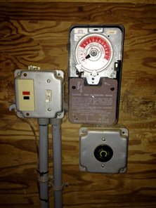
We have a typical mechanical timer (picture to be taken and attached later today) for our pool pump. This device simply turns the power on or off to the pump depending on the time of day/night. I would like to be able to set this functionality from my mobile device. Additional functionality is desired such as monitoring power draw, indicating clogged pump (heavy draw) or no water (low draw). and even the pi camera to view the basket attached to the pump.


The mobile app I will address elsewhere but the digital interface between the 110 volt circuit and the plug is confusing to me. Could this even be possible with a Pi (or a Pi and other accessories?) It seems possible in theory but in practice that may be another matter.


Thanks,

Vince


  • Sign in to reply
  • Cancel
  • dougw
    0 dougw over 11 years ago

    Hi Vince,

    Cool idea.

    I just designed a module based on an ARM Cortex M0 that has a Bluetooth interface, a GPS based real time clock and an optically isolated triac output. It also has a light sensor if you want to detect day/night. It could easily be programmed to control the pump schedule and a smart phone could be used to edit the schedule or directly control the pump. If your pump requires more than 1 amp, the the small triac in my module would need to drive a larger external triac or relay. I will likely be blogging about the module here in a week or so, although my application for it is a smart thermostat. I guess you could use a clamp-on current sensor to monitor pump current or you could use pressure sensors to monitor status.

    Doug

    • Cancel
    • Vote Up +1 Vote Down
    • Sign in to reply
    • Verify Answer
    • Cancel
  • Problemchild
    0 Problemchild over 11 years ago

    Get your self one of these (BV503) I've been playing with one ant they are cool!


    Just add one of those Relay boards that are all over the EBAYs  image


    The WIFI module  is a linux machine and you can even program it using a basic like language ...not bad at all!!!

    • Cancel
    • Vote Up +1 Vote Down
    • Sign in to reply
    • Verify Answer
    • Cancel
  • Problemchild
    0 Problemchild over 11 years ago in reply to dougw

    Douglas the Lack of an RTC  would be a pain and I for one have used GPS just for the RTC function however if you

    go for WIFI especially if the device is quite intelligent I would suggest saving the money and using  NTP protocol to set the time maybe even from your local router if  it supports it or more programatically have the GUI control app have the functionality to push the time to the dumb device or have it capable of polling the tablet

    • Cancel
    • Vote Up 0 Vote Down
    • Sign in to reply
    • Verify Answer
    • Cancel
  • vd0gg1t
    0 vd0gg1t over 11 years ago in reply to dougw

    Thanks Doug! This is just the direction and support I was looking for. My pump is 1 amp so that is good. I have a steep learning curve with relays (no experience at all) but necessity is the mother of invention. I will be looking for your blog and review the tutorials. more to come. (haven't forgotten about the picture just too busy fixing the pool connections. pvc, latex gloves and purple primer, yum! image)

    • Cancel
    • Vote Up 0 Vote Down
    • Sign in to reply
    • Verify Answer
    • Cancel
  • vd0gg1t
    0 vd0gg1t over 11 years ago in reply to Problemchild

    Hi John,


    The BV503 looks like a very interesting option. Why reinvent the wheel, right? As I posted to Doug, I need to gain some experience working with relays but your right, ebay does have a lot to choose from. Thanks for the pointers. Now I have to make some commitments.


    Thanks,

    Vince

    • Cancel
    • Vote Up 0 Vote Down
    • Sign in to reply
    • Verify Answer
    • Cancel
  • mconners
    0 mconners over 11 years ago in reply to vd0gg1t

    I agree that the BV503 looks like it would be fun to play with, but for the cost a raspi and Amazon.com: Edimax EW-7811Un 150 Mbps Wireless 11n Nano Size USB Adapter with EZmax Setup Wizard: Computers & Accessorie… may be a cheaper option. And you get the full power of an os underneath. As John did suggest you could use NTP to get the time. You could still add the relay boards as John also suggested.


    You might even be able to get by with the model A.


    Sounds like a fun project.


    Good Luck,

    Mike

    • Cancel
    • Vote Up 0 Vote Down
    • Sign in to reply
    • Verify Answer
    • Cancel
  • vd0gg1t
    0 vd0gg1t over 11 years ago in reply to mconners

    Hi Mike,


    Yes, this is similar to what they used in the raspberry pi videos, so that is what I was expecting to use. There is always a different configuration, the latest configuration may (or may not) be the best, and whatever is chosen will be obsolete by the time I am done but I need to decide on specifics soon. Thanks for your input, I like the K.I.S.S. principle. The BV503 is interesting but having the operating system available and an "open" approach the better for me at least at this point. updating original post next.


    thanks,

    Vince

    • Cancel
    • Vote Up 0 Vote Down
    • Sign in to reply
    • Verify Answer
    • Cancel
  • vd0gg1t
    0 vd0gg1t over 11 years ago

    ok, as promised here are the pics. This inside an unheated barn. (weatherproof but extreme temperatures may be a factor)

    Note: Switch is for pool light in deep end.


    Complete Setup                                                  Timer                                                       Schematic

             imageimageimage

    Intention: Replace "wheel" with raspberry Pi, an LCD display (for standalone operation), relay(?), and wifi. WiFi would allow the relay to be controlled remotely from a smartphone app.


    I can take further pictures for more specific detail if needed. (example, behind the timer wheel or more focus on tripping mechanism)


    Thanks,

    Vince

    • Cancel
    • Vote Up 0 Vote Down
    • Sign in to reply
    • Verify Answer
    • Cancel
  • Robert Peter Oakes
    0 Robert Peter Oakes over 11 years ago in reply to vd0gg1t

    As already suggested, I would not attempt to modify the existing timer device, it is just not worth the effort


    You will be better off creating a new control system from scratch


    first BIG issue is the load your switching (The diagram indicates a 40A switch is currently used, I would not suggest underrating the replacement as the startup currents will be quite excessive even if the normal running will probably be under 15-30A, most relay boards from E-Bay are rated around 5A


    A solid state relay will allow easy interfacing, Full isolation and easy mounting see this as an example Solid State Relay SSR 60Da 60A 3 32VDC 24 380VAC | eBay (I selected one that was over rated for safety reasons, You still should have a circuit breaker of course which I assume is elsewhere as it is not visible in your pictures. It can be driven from anything that can power an LED.


    image


    detecting the motor running is a little trickier, you could assume it is on based on the fact your controlling the relay or you can use a circuit like this

    image

    it could drive an interrupt or you could simply put a diode and rc network to smooth out the output to a logic level and simply have a low high signal. either way isolated and safe.(Adjust R1 to suit 110V if needed)


    for measuring the current I would start with something like this (Keeping with the isolated system for safety theme http://www.ebay.com/itm/Hall-Effect-Current-Sensor-For-Hobbyist-Arduino-Compatible-AC-75A-DC-100A-/231154766766?pt=LH_DefaultDomain_2&hash=item35d1e5d3ae


    image


    now of course being able to measure the current you could drop the voltage sensor as you will detect the current and this will indicate the motor should be running and also provide the current to the load


    there are plenty of circuits for driving a small 2 or 4 line LCD display with a PI so just google that for details


    all that's left is software and interfacing the analog front he sensor to the PI and again there are plenty of examples for that too. With the WIFI adapter suggested above, all this could be controlled remotely and is limited by your imagination


    btw, a smaller powered solid state relay could also be used to control the pool light you mention.


    sounds like a fun project, be safe and have fun

    • Cancel
    • Vote Up 0 Vote Down
    • Sign in to reply
    • Verify Answer
    • Cancel
  • vd0gg1t
    0 vd0gg1t over 11 years ago in reply to Robert Peter Oakes

    Thanks Peter!


    Sorry for the confusion. The circuit breaker is wired in the house. It is marked as 20 amps going to the pool but does take two punchouts. So is that 20 amps or 2x20 amps = 40? I have always gone by what is marked. (I might be overthinking this part. Also, I have manually flipped off this the circuit for this project.)


    image

    Keeping things isolated is definitely the way I want to go. My measurement concerns are for reliability and safety. The precision window is rather large.


    Also, I like your idea for a smaller solid state relay for the pool light. Additionally, Multicolor LED lights are now available (expensive) and can be programmed for variable light displays (white, rainbow, different patterns) depending upon the on/off combinations at the switch. Using a relay, we could remotely chose lighting patterns as well as on/off state. Getting ahead of myself.


    • Minimum Requirement: Update timer to have remote control to turn pump power on or off.
    • Additional Desired Functionality: monitoring flows and debris build up.
    • Nice To Have: Light Control.


    Honestly, once I gain confidence from completing the minimum requirement, the additional functionality and nice to have should follow up quite nicely. (just trying to keep perspective)


    Thanks Again, Peter. This should be an interesting week.

    • Cancel
    • Vote Up 0 Vote Down
    • Sign in to reply
    • Verify Answer
    • Cancel
>
element14 Community

element14 is the first online community specifically for engineers. Connect with your peers and get expert answers to your questions.

  • Members
  • Learn
  • Technologies
  • Challenges & Projects
  • Products
  • Store
  • About Us
  • Feedback & Support
  • FAQs
  • Terms of Use
  • Privacy Policy
  • Legal and Copyright Notices
  • Sitemap
  • Cookies

An Avnet Company © 2025 Premier Farnell Limited. All Rights Reserved.

Premier Farnell Ltd, registered in England and Wales (no 00876412), registered office: Farnell House, Forge Lane, Leeds LS12 2NE.

ICP 备案号 10220084.

Follow element14

  • X
  • Facebook
  • linkedin
  • YouTube