element14 Community
element14 Community
    Register Log In
  • Site
  • Search
  • Log In Register
  • About Us
  • Community Hub
    Community Hub
    • What's New on element14
    • Feedback and Support
    • Benefits of Membership
    • Personal Blogs
    • Members Area
    • Achievement Levels
  • Learn
    Learn
    • Ask an Expert
    • eBooks
    • element14 presents
    • Learning Center
    • Tech Spotlight
    • STEM Academy
    • Webinars, Training and Events
    • Learning Groups
  • Technologies
    Technologies
    • 3D Printing
    • FPGA
    • Industrial Automation
    • Internet of Things
    • Power & Energy
    • Sensors
    • Technology Groups
  • Challenges & Projects
    Challenges & Projects
    • Design Challenges
    • element14 presents Projects
    • Project14
    • Arduino Projects
    • Raspberry Pi Projects
    • Project Groups
  • Products
    Products
    • Arduino
    • Avnet Boards Community
    • Dev Tools
    • Manufacturers
    • Multicomp Pro
    • Product Groups
    • Raspberry Pi
    • RoadTests & Reviews
  • Store
    Store
    • Visit Your Store
    • Choose another store...
      • Europe
      •  Austria (German)
      •  Belgium (Dutch, French)
      •  Bulgaria (Bulgarian)
      •  Czech Republic (Czech)
      •  Denmark (Danish)
      •  Estonia (Estonian)
      •  Finland (Finnish)
      •  France (French)
      •  Germany (German)
      •  Hungary (Hungarian)
      •  Ireland
      •  Israel
      •  Italy (Italian)
      •  Latvia (Latvian)
      •  
      •  Lithuania (Lithuanian)
      •  Netherlands (Dutch)
      •  Norway (Norwegian)
      •  Poland (Polish)
      •  Portugal (Portuguese)
      •  Romania (Romanian)
      •  Russia (Russian)
      •  Slovakia (Slovak)
      •  Slovenia (Slovenian)
      •  Spain (Spanish)
      •  Sweden (Swedish)
      •  Switzerland(German, French)
      •  Turkey (Turkish)
      •  United Kingdom
      • Asia Pacific
      •  Australia
      •  China
      •  Hong Kong
      •  India
      •  Korea (Korean)
      •  Malaysia
      •  New Zealand
      •  Philippines
      •  Singapore
      •  Taiwan
      •  Thailand (Thai)
      • Americas
      •  Brazil (Portuguese)
      •  Canada
      •  Mexico (Spanish)
      •  United States
      Can't find the country/region you're looking for? Visit our export site or find a local distributor.
  • Translate
  • Profile
  • Settings
Raspberry Pi
  • Products
  • More
Raspberry Pi
Raspberry Pi Forum Want to create a capacitance proximity/touch sensor with a RP2040 Pico board using PIO
  • Blog
  • Forum
  • Documents
  • Quiz
  • Events
  • Polls
  • Files
  • Members
  • Mentions
  • Sub-Groups
  • Tags
  • More
  • Cancel
  • New
Join Raspberry Pi to participate - click to join for free!
Featured Articles
Announcing Pi
Technical Specifications
Raspberry Pi FAQs
Win a Pi
Raspberry Pi Wishlist
Actions
  • Share
  • More
  • Cancel
Forum Thread Details
  • State Not Answered
  • Replies 36 replies
  • Subscribers 662 subscribers
  • Views 12271 views
  • Users 0 members are here
  • proximity_sensors
  • rp2040
  • PIO
  • capacitive
Related

Want to create a capacitance proximity/touch sensor with a RP2040 Pico board using PIO

BigG
BigG over 3 years ago

There is nothing quite like solving a problem to help develop new skills. In this case I have found a library solution to what I want to achieve but it is not RP2040 compatible and of course it does not use PIO, which is the skill I am trying to acquire.

Having seen other members deliver some great PIO related projects, I thought this would be a great opportunity to build a solution together while helping me, and hopefully others, grasp how to develop PIO code from scratch.

Basically I want to create a capacitance touch or proximity sensor using a Raspberry Pi Pico (RP2040) board.

There is an Arduino library that can do this: https://github.com/PaulStoffregen/CapacitiveSensor

But it is not RP2040 compatible: https://github.com/PaulStoffregen/CapacitiveSensor/issues/42

Having reviewed this library, it appears on face value to be well suited to use PIO. Only, I don't know how to start.

As far as I can make out, there is only one function to apply PIO... but maybe others see things differently. I'm keen to learn more.

// Private Methods /////////////////////////////////////////////////////////////
// Functions only available to other functions in this library

int CapacitiveSensor::SenseOneCycle(void)
{
    noInterrupts();
	DIRECT_WRITE_LOW(sReg, sBit);	// sendPin Register low
	DIRECT_MODE_INPUT(rReg, rBit);	// receivePin to input (pullups are off)
	DIRECT_MODE_OUTPUT(rReg, rBit); // receivePin to OUTPUT
	DIRECT_WRITE_LOW(rReg, rBit);	// pin is now LOW AND OUTPUT
	delayMicroseconds(10);
	DIRECT_MODE_INPUT(rReg, rBit);	// receivePin to input (pullups are off)
	DIRECT_WRITE_HIGH(sReg, sBit);	// sendPin High
    interrupts();

	while ( !DIRECT_READ(rReg, rBit) && (total < CS_Timeout_Millis) ) {  // while receive pin is LOW AND total is positive value
		total++;
	}
	//Serial.print("SenseOneCycle(1): ");
	//Serial.println(total);

	if (total > CS_Timeout_Millis) {
		return -2;         //  total variable over timeout
	}

	// set receive pin HIGH briefly to charge up fully - because the while loop above will exit when pin is ~ 2.5V
    noInterrupts();
	DIRECT_WRITE_HIGH(rReg, rBit);
	DIRECT_MODE_OUTPUT(rReg, rBit);  // receivePin to OUTPUT - pin is now HIGH AND OUTPUT
	DIRECT_WRITE_HIGH(rReg, rBit);
	DIRECT_MODE_INPUT(rReg, rBit);	// receivePin to INPUT (pullup is off)
	DIRECT_WRITE_LOW(sReg, sBit);	// sendPin LOW
    interrupts();

#ifdef FIVE_VOLT_TOLERANCE_WORKAROUND
	DIRECT_MODE_OUTPUT(rReg, rBit);
	DIRECT_WRITE_LOW(rReg, rBit);
	delayMicroseconds(10);
	DIRECT_MODE_INPUT(rReg, rBit);	// receivePin to INPUT (pullup is off)
#else
	while ( DIRECT_READ(rReg, rBit) && (total < CS_Timeout_Millis) ) {  // while receive pin is HIGH  AND total is less than timeout
		total++;
	}
#endif
	//Serial.print("SenseOneCycle(2): ");
	//Serial.println(total);

	if (total >= CS_Timeout_Millis) {
		return -2;     // total variable over timeout
	} else {
		return 1;
	}
}

  • Sign in to reply
  • Cancel
Parents
  • scottiebabe
    0 scottiebabe over 3 years ago

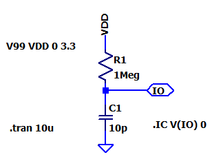
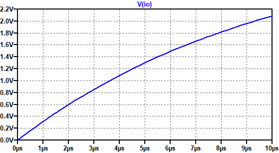
    Hello, I'm a hardware gal and can't make heads or tails of that library. I'm not sure why you need 2 GPIO pins. I assume the author is trying to measure the charge time of the capacitance seen on a GPIO pin. So something like this,

    image image

    So presumably, the GPIO pin can output low to reset the effective capacitance on the pin. Then go Hi-Z and measure the time taken for the capacitance to charge to a VIH threshold.

    I'm not sure I know the PIO module well enough to write a how-to guide, but I am happy to answer questions to the best of my knowledge, because I think the PIO module is pretty neat.

    • Cancel
    • Vote Up +3 Vote Down
    • Sign in to reply
    • Verify Answer
    • Cancel
  • scottiebabe
    0 scottiebabe over 3 years ago in reply to scottiebabe

    Thank you so much for opening this discussion, it has helped me quite a bit too! I gave the single IO pin with pullup resistor a try and I think it works okay:

    # PIO Capsense experiment
    # -scottiebabe 2022
    import time
    from machine import Pin
    import rp2
    
    machine.freq(125_000_000)
    
    # Ensure pin pull-ups and pull-downs are disabled
    # So pin is Hi-Z when set as input
    Pin(28,Pin.IN)
    
    @rp2.asm_pio(set_init=[rp2.PIO.OUT_LOW])
    def capsense():
        set(pindirs, 1) # set GPIO as output
        set(pins, 0)
        set(x,24)
        label('dischargeloop') #wait (24+1)*5 = 125 cycles (1 us)
        jmp( x_dec, 'dischargeloop') [4]
        mov(isr,null) # clear ISR, not sure if this is required
        set(x,1) #  x = 1
        in_(x,1) # shift x into isr
        in_(null,12) # shift 12 0's into isr
        mov(x,isr)   # set x = 1<<12 (4096)
        set(pindirs, 0)     # set GPIO as input
        label('timing')
        jmp(pin,'done')     # breakout of timing loop when pin reads high
        jmp(x_dec,'timing') # decrement x until timeout
        label('done')
        mov(isr,x)          # load ISR with count value in x
        push(noblock)       # push ISR into RX fifo
    
    # Create the StateMachine with the capsense program, using pin28.
    sm = rp2.StateMachine(0, capsense, freq=125_000_000, set_base=Pin(28),jmp_pin=Pin(28))
    
    
    # Start the StateMachine.
    sm.active(1)
    
    while True:
        print(sm.get())
        time.sleep(0.05)
     

    Happy to explain or clarify or be corrected (I don't consider myself a PIO expert yet LOL) 

    • Cancel
    • Vote Up +2 Vote Down
    • Sign in to reply
    • Verify Answer
    • Cancel
  • BigG
    0 BigG over 3 years ago in reply to scottiebabe

    Brilliant. Well done. I'm going to try and convert that to C and see how I can get it to work.

    It just so happens that I just discovered another capacitive sensor library that does things slightly differently by using AnalogRead (in Arduino) via analog pins to calculate capacitive values. At least this one works straight out the box with the Pico board.

    https://github.com/Nyanyan/FastCapacitiveSensor

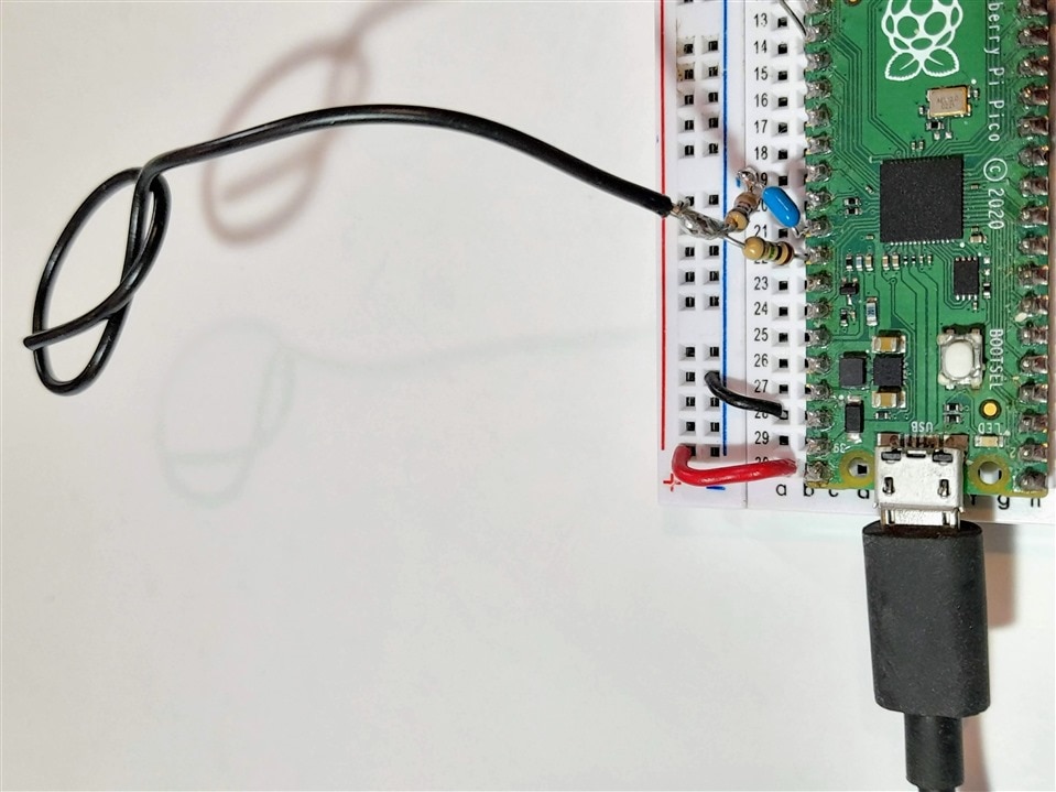
    In fact I came up with my own circuit, which still gave me pretty good non-contact sensitivity as I didn't have any resistors greater than 1M ohm.

    {gallery}Capacitive Pico

    image

    image

    It will be interesting to compare this test with the other library (once got working with PIO) and maybe also convert this new library to PIO if possible to see if any improved performance.

    Still lots to learn...

    • Cancel
    • Vote Up +2 Vote Down
    • Sign in to reply
    • Verify Answer
    • Cancel
  • scottiebabe
    0 scottiebabe over 3 years ago in reply to BigG

    Kudos to you for taking on the PIO, It feels pretty awesome when you get first statemachine program to work.

    Very neat, I haven't seen a capsense implementation like that before. I'm also impressed the ADC can sample such a high-impedance source so reliably, very cool! 

    • Cancel
    • Vote Up +1 Vote Down
    • Sign in to reply
    • Verify Answer
    • Cancel
  • scottiebabe
    0 scottiebabe over 3 years ago in reply to scottiebabe

    Hmm pushing to a full fifo results in the push being discarded, it doesn't overwrite values in the fifo. So the sm.get() isn't the most recent result. 

    • Cancel
    • Vote Up 0 Vote Down
    • Sign in to reply
    • Verify Answer
    • Cancel
  • BigG
    0 BigG over 3 years ago in reply to BigG

    I had to make a small modification to the fast capacitive sensing library as it is targeting Arduino UNO (5V and 10bit ADC resolution).

    So this line was changed: double INPUTTHRESHOLD = VOLTAGE * 4096 / 3.3 * 0.9;

    Then I applied quite a bit of sampling by using min and max values to generate my psuedo capacitive values.

    Here's my Pico Arduino code (first hack version):

    /* Arduino Code of Raspberry Pi Pico board
     * MIT License
     * 
     * Copyright (c) C Gerrish (BigG) - relates to this example
     * 
     * Example is based on a modified version of this library:
     * https://github.com/Nyanyan/FastCapacitiveSensor
     * 
     * The following was changed in the library:
     * double INPUTTHRESHOLD = VOLTAGE * 4096 / 3.3 * 0.9;
     * 
     * Permission is hereby granted, free of charge, to any person obtaining a copy
     * of this software and associated documentation files (the "Software"), to deal
     * in the Software without restriction, including without limitation the rights
     * to use, copy, modify, merge, publish, distribute, sublicense, and/or sell
     * copies of the Software, and to permit persons to whom the Software is
     * furnished to do so, subject to the following conditions:
     * 
     * The above copyright notice and this permission notice shall be included in all
     * copies or substantial portions of the Software.
     * 
     * THE SOFTWARE IS PROVIDED "AS IS", WITHOUT WARRANTY OF ANY KIND, EXPRESS OR
     * IMPLIED, INCLUDING BUT NOT LIMITED TO THE WARRANTIES OF MERCHANTABILITY,
     * FITNESS FOR A PARTICULAR PURPOSE AND NONINFRINGEMENT. IN NO EVENT SHALL THE
     * AUTHORS OR COPYRIGHT HOLDERS BE LIABLE FOR ANY CLAIM, DAMAGES OR OTHER
     * LIABILITY, WHETHER IN AN ACTION OF CONTRACT, TORT OR OTHERWISE, ARISING FROM,
     * OUT OF OR IN CONNECTION WITH THE SOFTWARE OR THE USE OR OTHER DEALINGS IN THE
     * SOFTWARE.
     *  
     */
     
    #include <FastCapacitiveSensor.h>
    FastCapacitiveSensor sensor1;
    
    const byte MAXSAMPLES = 10;
    
    void setup() {
      pinMode(A1, OUTPUT);
      pinMode(A0, INPUT);
      Serial.begin(115200);
      sensor1.begin(A0, A1, 3.3, 10, 10, 0.2);
    }
    
    int cntr = 0;
    long tmax = 0;
    long tmin = 0xffffffff;
    
    int smplCntr = 0;
    long samples[MAXSAMPLES];
    
    bool sampleRdy = false;
    
    void loop() {
      long t = long(sensor1.touch());
      if (cntr == MAXSAMPLES) {
        if (smplCntr == MAXSAMPLES) {
          if (!sampleRdy) sampleRdy = true;
          smplCntr = 0;
        }
        if (sampleRdy) {
          long totval = 0;
          for (byte i = 0; i < MAXSAMPLES; i++) {
            totval += samples[i];
          }
          // This is for the Serial Plotter and to make sure 0 is minimum value on y-axis
          Serial.print(0); Serial.print(",");
          Serial.println(totval/MAXSAMPLES);
        }
        samples[smplCntr] = tmax - tmin;
        smplCntr++;
        cntr = 0;
        tmax = 0;
        tmin = 0xffffffff;        
      }
      if (t < tmin) tmin = t;
      if (t > tmax) tmax = t;
      cntr++;
    }

    Here's a short video (no audio) showing the Arduino Serial Plotter output:

    You don't have permission to edit metadata of this video.
    Edit media
    x
    image
    Upload Preview
    image

    No doubt this could be improved upon. It's a start at least.

    • Cancel
    • Vote Up +3 Vote Down
    • Sign in to reply
    • Verify Answer
    • Cancel
Reply
  • BigG
    0 BigG over 3 years ago in reply to BigG

    I had to make a small modification to the fast capacitive sensing library as it is targeting Arduino UNO (5V and 10bit ADC resolution).

    So this line was changed: double INPUTTHRESHOLD = VOLTAGE * 4096 / 3.3 * 0.9;

    Then I applied quite a bit of sampling by using min and max values to generate my psuedo capacitive values.

    Here's my Pico Arduino code (first hack version):

    /* Arduino Code of Raspberry Pi Pico board
     * MIT License
     * 
     * Copyright (c) C Gerrish (BigG) - relates to this example
     * 
     * Example is based on a modified version of this library:
     * https://github.com/Nyanyan/FastCapacitiveSensor
     * 
     * The following was changed in the library:
     * double INPUTTHRESHOLD = VOLTAGE * 4096 / 3.3 * 0.9;
     * 
     * Permission is hereby granted, free of charge, to any person obtaining a copy
     * of this software and associated documentation files (the "Software"), to deal
     * in the Software without restriction, including without limitation the rights
     * to use, copy, modify, merge, publish, distribute, sublicense, and/or sell
     * copies of the Software, and to permit persons to whom the Software is
     * furnished to do so, subject to the following conditions:
     * 
     * The above copyright notice and this permission notice shall be included in all
     * copies or substantial portions of the Software.
     * 
     * THE SOFTWARE IS PROVIDED "AS IS", WITHOUT WARRANTY OF ANY KIND, EXPRESS OR
     * IMPLIED, INCLUDING BUT NOT LIMITED TO THE WARRANTIES OF MERCHANTABILITY,
     * FITNESS FOR A PARTICULAR PURPOSE AND NONINFRINGEMENT. IN NO EVENT SHALL THE
     * AUTHORS OR COPYRIGHT HOLDERS BE LIABLE FOR ANY CLAIM, DAMAGES OR OTHER
     * LIABILITY, WHETHER IN AN ACTION OF CONTRACT, TORT OR OTHERWISE, ARISING FROM,
     * OUT OF OR IN CONNECTION WITH THE SOFTWARE OR THE USE OR OTHER DEALINGS IN THE
     * SOFTWARE.
     *  
     */
     
    #include <FastCapacitiveSensor.h>
    FastCapacitiveSensor sensor1;
    
    const byte MAXSAMPLES = 10;
    
    void setup() {
      pinMode(A1, OUTPUT);
      pinMode(A0, INPUT);
      Serial.begin(115200);
      sensor1.begin(A0, A1, 3.3, 10, 10, 0.2);
    }
    
    int cntr = 0;
    long tmax = 0;
    long tmin = 0xffffffff;
    
    int smplCntr = 0;
    long samples[MAXSAMPLES];
    
    bool sampleRdy = false;
    
    void loop() {
      long t = long(sensor1.touch());
      if (cntr == MAXSAMPLES) {
        if (smplCntr == MAXSAMPLES) {
          if (!sampleRdy) sampleRdy = true;
          smplCntr = 0;
        }
        if (sampleRdy) {
          long totval = 0;
          for (byte i = 0; i < MAXSAMPLES; i++) {
            totval += samples[i];
          }
          // This is for the Serial Plotter and to make sure 0 is minimum value on y-axis
          Serial.print(0); Serial.print(",");
          Serial.println(totval/MAXSAMPLES);
        }
        samples[smplCntr] = tmax - tmin;
        smplCntr++;
        cntr = 0;
        tmax = 0;
        tmin = 0xffffffff;        
      }
      if (t < tmin) tmin = t;
      if (t > tmax) tmax = t;
      cntr++;
    }

    Here's a short video (no audio) showing the Arduino Serial Plotter output:

    You don't have permission to edit metadata of this video.
    Edit media
    x
    image
    Upload Preview
    image

    No doubt this could be improved upon. It's a start at least.

    • Cancel
    • Vote Up +3 Vote Down
    • Sign in to reply
    • Verify Answer
    • Cancel
Children
  • BigG
    0 BigG over 3 years ago in reply to BigG

    I digressed a little from my PIO development plans, only because I decided for some reason to cut an inch off the wire. This totally changed detection sensitivity and now it was only able to detect touch rather than proximity... basically this is a classic case of hardware changes overruling any software methodology. I am going to have to replace or modify again to return to my original objective of proximity detection.

    Anyway, I modified my code to determine state change. Works pretty well.

    /* Arduino Code of Raspberry Pi Pico board
     *  This code determines state change of a capacitive touch sensor
     *  
     * MIT License applies
     * 
     * Copyright (c) C Gerrish (BigG) - relates to this example
     * 
     * Example is based on a modified version of this library:
     * https://github.com/Nyanyan/FastCapacitiveSensor
     * 
     * The following was changed in the library:
     * double INPUTTHRESHOLD = VOLTAGE * 4096 / 3.3 * 0.9;
     * 
     * Permission is hereby granted, free of charge, to any person obtaining a copy
     * of this software and associated documentation files (the "Software"), to deal
     * in the Software without restriction, including without limitation the rights
     * to use, copy, modify, merge, publish, distribute, sublicense, and/or sell
     * copies of the Software, and to permit persons to whom the Software is
     * furnished to do so, subject to the following conditions:
     * 
     * The above copyright notice and this permission notice shall be included in all
     * copies or substantial portions of the Software.
     * 
     * THE SOFTWARE IS PROVIDED "AS IS", WITHOUT WARRANTY OF ANY KIND, EXPRESS OR
     * IMPLIED, INCLUDING BUT NOT LIMITED TO THE WARRANTIES OF MERCHANTABILITY,
     * FITNESS FOR A PARTICULAR PURPOSE AND NONINFRINGEMENT. IN NO EVENT SHALL THE
     * AUTHORS OR COPYRIGHT HOLDERS BE LIABLE FOR ANY CLAIM, DAMAGES OR OTHER
     * LIABILITY, WHETHER IN AN ACTION OF CONTRACT, TORT OR OTHERWISE, ARISING FROM,
     * OUT OF OR IN CONNECTION WITH THE SOFTWARE OR THE USE OR OTHER DEALINGS IN THE
     * SOFTWARE.
     *  
     */
     
    #include <FastCapacitiveSensor.h>
    
    
    #define LEDPIN    20
    
    // Number of samples taken
    const byte MAXSAMPLES = 10;
    
    // Number of values used to calibrate
    // Using 30 samples to calibrate base level in order to normalise to zero for no touch
    const byte CALIBSAMPLES = 30;
    
    // 20,000 seemed to be best fit to get my touch easily recognised (adjust to suit your setup)
    // if too sensitive then raise value or if not sensitive enough then reduce value
    const int MAXCAPVALUE = 20000;
    
    FastCapacitiveSensor sensor1;
    
    void setup() {
      pinMode(A1, OUTPUT);
      pinMode(A0, INPUT);
      pinMode(LEDPIN,OUTPUT);
      
      Serial.begin(115200);
      sensor1.begin(A0, A1, 3.3, 10, 10, 0.2);
    }
    
    int cntr = 0;
    long tmax = 0;
    long tmin = 0xffffffff;
    
    int smplCntr = 0;
    long samples[MAXSAMPLES];
    
    int caliCntr = 0;
    long calibrate = 0;
    
    bool sampleRdy = false;
    bool caliRdy = false;
    
    bool CapDect = false;
    bool PrevDect = false;
    
    void loop() {
      long t = long(sensor1.touch());
      if (cntr == MAXSAMPLES) {
        if (smplCntr == MAXSAMPLES) {
          if (!sampleRdy) sampleRdy = true;
          smplCntr = 0;
        }
        if (sampleRdy) {
          long totval = 0;
          for (byte i = 0; i < MAXSAMPLES; i++) {
            totval += samples[i];
          }
          if (caliCntr < CALIBSAMPLES) {
            calibrate += totval/MAXSAMPLES;
            caliCntr++;
          }
          else {
            if (!caliRdy) {
              caliRdy = true;
              calibrate /= CALIBSAMPLES;
            }
            // Using constrain to limit min and max values to 0 and MAXCAPVALUE    
            totval = constrain(totval/MAXSAMPLES - calibrate, 0, MAXCAPVALUE);
            // Using map as a way to show a 0 to 100 representation
            // So basically if >70% then taken as touch otherwise sensor not touched
            CapDect = map(totval,0,MAXCAPVALUE,0,100)>70?true:false;
            
            // Showing change of state on Serial Monitor
            if (CapDect != PrevDect) {
              if (CapDect) {
                Serial.println("ON");
                digitalWrite(LEDPIN, HIGH);
              }
              else {
                Serial.println("OFF");
                digitalWrite(LEDPIN, LOW);
              }
            }
            
            PrevDect = CapDect;
            
          }
        }
        samples[smplCntr] = tmax - tmin;
        smplCntr++;
        cntr = 0;
        tmax = 0;
        tmin = 0xffffffff;        
      }
      if (t < tmin) tmin = t;
      if (t > tmax) tmax = t;
      cntr++;
    }

    Here's a short no audio video demo (note camera buffer seemed to create a lag behind serial output for some reason - as such LED seems out of sync in video):

    You don't have permission to edit metadata of this video.
    Edit media
    x
    image
    Upload Preview
    image

    • Cancel
    • Vote Up +3 Vote Down
    • Sign in to reply
    • Verify Answer
    • Cancel
element14 Community

element14 is the first online community specifically for engineers. Connect with your peers and get expert answers to your questions.

  • Members
  • Learn
  • Technologies
  • Challenges & Projects
  • Products
  • Store
  • About Us
  • Feedback & Support
  • FAQs
  • Terms of Use
  • Privacy Policy
  • Legal and Copyright Notices
  • Sitemap
  • Cookies

An Avnet Company © 2025 Premier Farnell Limited. All Rights Reserved.

Premier Farnell Ltd, registered in England and Wales (no 00876412), registered office: Farnell House, Forge Lane, Leeds LS12 2NE.

ICP 备案号 10220084.

Follow element14

  • X
  • Facebook
  • linkedin
  • YouTube