element14 Community
element14 Community
    Register Log In
  • Site
  • Search
  • Log In Register
  • About Us
  • Community Hub
    Community Hub
    • What's New on element14
    • Feedback and Support
    • Benefits of Membership
    • Personal Blogs
    • Members Area
    • Achievement Levels
  • Learn
    Learn
    • Ask an Expert
    • eBooks
    • element14 presents
    • Learning Center
    • Tech Spotlight
    • STEM Academy
    • Webinars, Training and Events
    • Learning Groups
  • Technologies
    Technologies
    • 3D Printing
    • FPGA
    • Industrial Automation
    • Internet of Things
    • Power & Energy
    • Sensors
    • Technology Groups
  • Challenges & Projects
    Challenges & Projects
    • Design Challenges
    • element14 presents Projects
    • Project14
    • Arduino Projects
    • Raspberry Pi Projects
    • Project Groups
  • Products
    Products
    • Arduino
    • Avnet Boards Community
    • Dev Tools
    • Manufacturers
    • Multicomp Pro
    • Product Groups
    • Raspberry Pi
    • RoadTests & Reviews
  • Store
    Store
    • Visit Your Store
    • Choose another store...
      • Europe
      •  Austria (German)
      •  Belgium (Dutch, French)
      •  Bulgaria (Bulgarian)
      •  Czech Republic (Czech)
      •  Denmark (Danish)
      •  Estonia (Estonian)
      •  Finland (Finnish)
      •  France (French)
      •  Germany (German)
      •  Hungary (Hungarian)
      •  Ireland
      •  Israel
      •  Italy (Italian)
      •  Latvia (Latvian)
      •  
      •  Lithuania (Lithuanian)
      •  Netherlands (Dutch)
      •  Norway (Norwegian)
      •  Poland (Polish)
      •  Portugal (Portuguese)
      •  Romania (Romanian)
      •  Russia (Russian)
      •  Slovakia (Slovak)
      •  Slovenia (Slovenian)
      •  Spain (Spanish)
      •  Sweden (Swedish)
      •  Switzerland(German, French)
      •  Turkey (Turkish)
      •  United Kingdom
      • Asia Pacific
      •  Australia
      •  China
      •  Hong Kong
      •  India
      •  Korea (Korean)
      •  Malaysia
      •  New Zealand
      •  Philippines
      •  Singapore
      •  Taiwan
      •  Thailand (Thai)
      • Americas
      •  Brazil (Portuguese)
      •  Canada
      •  Mexico (Spanish)
      •  United States
      Can't find the country/region you're looking for? Visit our export site or find a local distributor.
  • Translate
  • Profile
  • Settings
Raspberry Pi
  • Products
  • More
Raspberry Pi
Raspberry Pi Forum Want to create a capacitance proximity/touch sensor with a RP2040 Pico board using PIO
  • Blog
  • Forum
  • Documents
  • Quiz
  • Events
  • Polls
  • Files
  • Members
  • Mentions
  • Sub-Groups
  • Tags
  • More
  • Cancel
  • New
Join Raspberry Pi to participate - click to join for free!
Featured Articles
Announcing Pi
Technical Specifications
Raspberry Pi FAQs
Win a Pi
Raspberry Pi Wishlist
Actions
  • Share
  • More
  • Cancel
Forum Thread Details
  • State Not Answered
  • Replies 36 replies
  • Subscribers 660 subscribers
  • Views 11884 views
  • Users 0 members are here
  • proximity_sensors
  • rp2040
  • PIO
  • capacitive
Related

Want to create a capacitance proximity/touch sensor with a RP2040 Pico board using PIO

BigG
BigG over 3 years ago

There is nothing quite like solving a problem to help develop new skills. In this case I have found a library solution to what I want to achieve but it is not RP2040 compatible and of course it does not use PIO, which is the skill I am trying to acquire.

Having seen other members deliver some great PIO related projects, I thought this would be a great opportunity to build a solution together while helping me, and hopefully others, grasp how to develop PIO code from scratch.

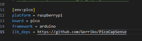
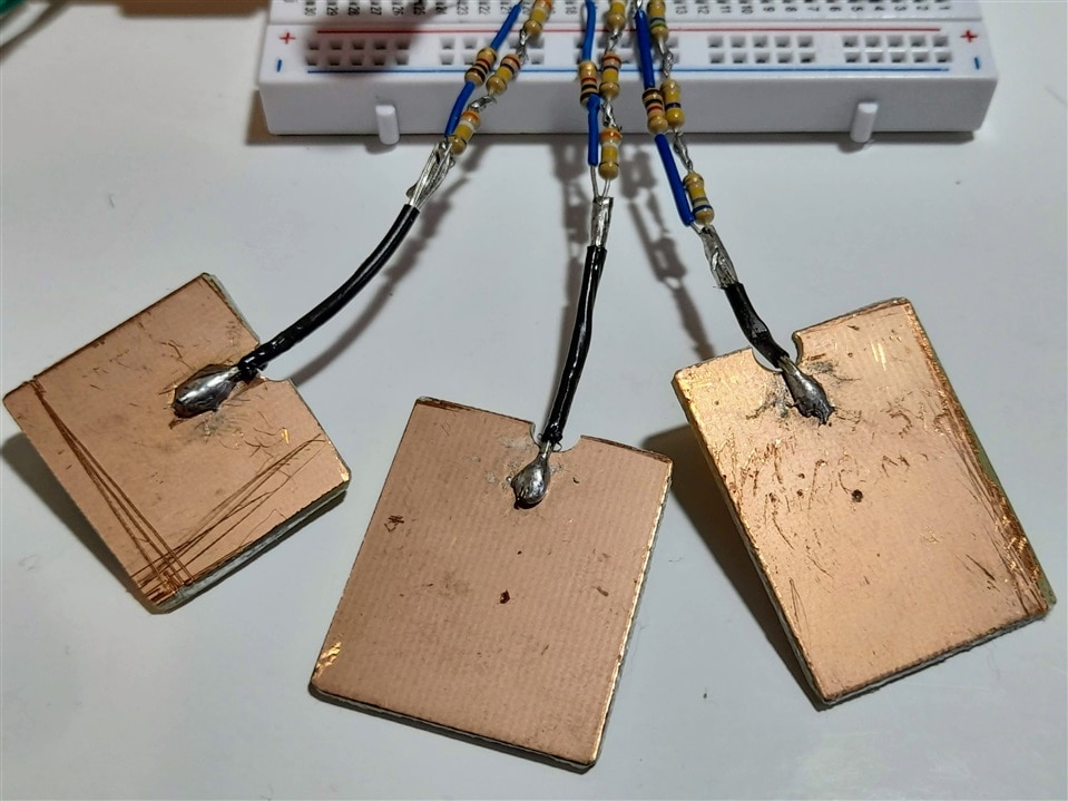
Basically I want to create a capacitance touch or proximity sensor using a Raspberry Pi Pico (RP2040) board.

There is an Arduino library that can do this: https://github.com/PaulStoffregen/CapacitiveSensor

But it is not RP2040 compatible: https://github.com/PaulStoffregen/CapacitiveSensor/issues/42

Having reviewed this library, it appears on face value to be well suited to use PIO. Only, I don't know how to start.

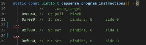
As far as I can make out, there is only one function to apply PIO... but maybe others see things differently. I'm keen to learn more.

// Private Methods /////////////////////////////////////////////////////////////
// Functions only available to other functions in this library

int CapacitiveSensor::SenseOneCycle(void)
{
    noInterrupts();
	DIRECT_WRITE_LOW(sReg, sBit);	// sendPin Register low
	DIRECT_MODE_INPUT(rReg, rBit);	// receivePin to input (pullups are off)
	DIRECT_MODE_OUTPUT(rReg, rBit); // receivePin to OUTPUT
	DIRECT_WRITE_LOW(rReg, rBit);	// pin is now LOW AND OUTPUT
	delayMicroseconds(10);
	DIRECT_MODE_INPUT(rReg, rBit);	// receivePin to input (pullups are off)
	DIRECT_WRITE_HIGH(sReg, sBit);	// sendPin High
    interrupts();

	while ( !DIRECT_READ(rReg, rBit) && (total < CS_Timeout_Millis) ) {  // while receive pin is LOW AND total is positive value
		total++;
	}
	//Serial.print("SenseOneCycle(1): ");
	//Serial.println(total);

	if (total > CS_Timeout_Millis) {
		return -2;         //  total variable over timeout
	}

	// set receive pin HIGH briefly to charge up fully - because the while loop above will exit when pin is ~ 2.5V
    noInterrupts();
	DIRECT_WRITE_HIGH(rReg, rBit);
	DIRECT_MODE_OUTPUT(rReg, rBit);  // receivePin to OUTPUT - pin is now HIGH AND OUTPUT
	DIRECT_WRITE_HIGH(rReg, rBit);
	DIRECT_MODE_INPUT(rReg, rBit);	// receivePin to INPUT (pullup is off)
	DIRECT_WRITE_LOW(sReg, sBit);	// sendPin LOW
    interrupts();

#ifdef FIVE_VOLT_TOLERANCE_WORKAROUND
	DIRECT_MODE_OUTPUT(rReg, rBit);
	DIRECT_WRITE_LOW(rReg, rBit);
	delayMicroseconds(10);
	DIRECT_MODE_INPUT(rReg, rBit);	// receivePin to INPUT (pullup is off)
#else
	while ( DIRECT_READ(rReg, rBit) && (total < CS_Timeout_Millis) ) {  // while receive pin is HIGH  AND total is less than timeout
		total++;
	}
#endif
	//Serial.print("SenseOneCycle(2): ");
	//Serial.println(total);

	if (total >= CS_Timeout_Millis) {
		return -2;     // total variable over timeout
	} else {
		return 1;
	}
}

  • Sign in to reply
  • Cancel
Parents
  • BigG
    0 BigG over 3 years ago

    Wow! I finally got my head around this PIO programming...

    For me it wasn't the PIO code side that was tricky. It was the program initialisation function that got me. Working out how to define GPIO's functions, states and pin directions was the hard bit.... looking at my code, as I write this, I probably didn't need to set the JMP pin.

    So I THINK I have this working.

    I have basically replicated the CapacitiveSensor::SenseOneCycle(void) function as closely as I could (hence you'll see a nop for a side set - you'll what this means once you've grasped PIO!).

    To do this I created 2 PIO routines using 2 state machines with the same trigger and receive GPIO's (as defined by sReg and rReg, respectively). This only works in blocking mode.

    ;
    ; Copyright (c) 2020 Raspberry Pi (Trading) Ltd.
    ;
    ; SPDX-License-Identifier: BSD-3-Clause
    ;
    
    .program capsense1
    .side_set 1 opt
    
    ; Initialise READ pin with TRIG pin for capsense timing detection
    
    begin1:
        pull                    ; used as a manual trigger
        nop             side 0  ; Trig Pin write low
        set pindirs, 0          ; Read Pin set as input
        set pindirs, 1          ; Read Pin set as output
        set pins, 0             ; Read Pin set low as an output
                        ; delay for 10 us (the length of the trigger pulse)
        set x 19        ; set x to 10011 (and clear the higher bits)
        mov ISR x       ; copy x to ISR
        in NULL 6       ; shift in 6 more 0 bits
        mov x ISR       ; move the ISR to x (which now contains 10011000000)
    delay1:
        jmp x-- delay1  ; count down to 0: a delay of (about) 10 us
        set pindirs, 0          ; Read Pin set as input
        nop             side 1  ; Trig Pin write high
        jmp begin1
    
    .program capsense2
    .side_set 1 opt
    
    ; Initialise READ pin with TRIG pin for capsense timing detection
    
    begin2:
        pull                    ; used as a manual trigger
        nop             side 0  ; Trig Pin write low
        set pins, 1             ; set Read Pin high as input
        set pindirs, 1          ; set Read Pin as output
        set pins, 1             ; set Read Pin high as input
        set pindirs, 0          ; set Read Pin as input
        nop             side 0  ; Trig Pin write low
        jmp begin2


    % c-sdk {
    // this is a raw helper function for use by the user which sets up the GPIO output, and configures the SM to output on a particular pin
    void capsense_program_init(PIO pio, uint sm1, uint offset1, uint sm2, uint offset2, uint trig_pin, uint read_pin) {
    
      uint32_t pins_assigned = (1u << trig_pin) | (1u << read_pin);
      uint32_t pins_setstate = (0u << trig_pin) | (0u << read_pin);
      uint32_t pins_setdirection = (1u << trig_pin) | (1u << read_pin);
    
      gpio_set_pulls(read_pin, false, false);         // make sure internal pull-up / pull-down not enabled
    
      pio_sm_set_pins_with_mask(pio, sm1, pins_setstate, pins_assigned);
      pio_sm_set_pindirs_with_mask(pio, sm1, pins_setdirection, pins_assigned);
      pio_sm_set_pins_with_mask(pio, sm2, pins_setstate, pins_assigned);
      pio_sm_set_pindirs_with_mask(pio, sm2, pins_setdirection, pins_assigned);
      pio_gpio_init(pio, trig_pin);
      pio_gpio_init(pio, read_pin);
    
      pio_sm_config c1 = capsense1_program_get_default_config(offset1);
      pio_sm_config c2 = capsense2_program_get_default_config(offset2);
      // use set config for the read pin to allow direction and state to change
      sm_config_set_set_pins(&c1, read_pin, 1);
      sm_config_set_set_pins(&c2, read_pin, 1);
      // set the 'jmp' pin to the read_pin to allow checks on state during timer
      sm_config_set_jmp_pin(&c1, read_pin);
      sm_config_set_jmp_pin(&c2, read_pin);
      // use out and sideset config for the trig pin to allow output state to change in parallel with read_pin
      sm_config_set_sideset_pins(&c1, trig_pin);
      sm_config_set_sideset_pins(&c2, trig_pin);
    
      // Load our configuration, and jump to the start of the program
      pio_sm_init(pio, sm1, offset1, &c1);
      pio_sm_init(pio, sm2, offset2, &c2);
      // Set the state machine running
      pio_sm_set_enabled(pio, sm1, true);
      pio_sm_set_enabled(pio, sm2, true);
    
    }
    %}

    I created an Arduino sketch to test it out.

    #include "hardware/pio.h"
    #include "hardware/clocks.h"
    
    #include "capsense.pio.h"
    
    #define F_CPU 125000000         // Assuming 125MHz for the Pico
    
    static const uint32_t CS_Timeout_Millis = (2000 * (float)310 * (float)F_CPU) / 16000000;;
    
    
    // additional LED pin numbers:
    static const int TRIGPIN =  13;// the number of the LED pin
    static const int RECPIN =  12;// the number of the LED pin
    PIO pio = pio0;
    
    // Find a free state machine on our chosen PIO (erroring if there are
    // none). Configure it to run our program, and start it, using the
    // helper function we included in our .pio file.
    unsigned int sm1 = 0;
    unsigned int sm2 = 0;
    
    uint32_t captimer = 0L;
    
    void setup() {
      // put your setup code here, to run once:
      // put your setup code here, to run once:
      Serial.begin(115200);
      while(!Serial) {;;}
      
      uint offset1 = pio_add_program(pio, &capsense1_program);
      Serial.println("Loaded program1 at "+String(offset1));
    
      uint offset2 = pio_add_program(pio, &capsense2_program);
      Serial.println("Loaded program1 at "+String(offset2));
    
      sm1 = pio_claim_unused_sm(pio, true);
      Serial.println("A free state machine instance for our 1st routine was set as "+String(sm1));
      sm2 = pio_claim_unused_sm(pio, true);
      Serial.println("A free state machine instance for our 2nd routine was set as "+String(sm2));
      
      capsense_program_init(pio, sm1, offset1, sm2, offset2, TRIGPIN, RECPIN);
      Serial.println("Capsense PIO instance now initialised");
    
    }
    
    void loop() {
      uint32_t total = 0L;
      captimer = micros();
      
      pio_sm_put_blocking(pio, sm1, 0);         // This triggers the first PIO routine
      
      while (!digitalRead(RECPIN) && (total < CS_Timeout_Millis)) {  // while receive pin is HIGH  AND total is less than timeout
       total++;
      }
      if (total <= CS_Timeout_Millis) {
         
        pio_sm_put_blocking(pio, sm2, 0);       // This triggers the 2nd PIO routine
        
        while (digitalRead(RECPIN) && (total < CS_Timeout_Millis)) {  // while receive pin is HIGH  AND total is less than timeout
          total++;
        }
        if (total <= CS_Timeout_Millis) {
          Serial.println("CapSensing Time: "+String(micros()-captimer));
        }
        else {
          Serial.println("CapSensing Timeout");
        }
      }
      delay(500);
    
    }

    And the PIO (capsense.pio.h) library is as follows:

    // -------------------------------------------------- //
    // This file is autogenerated by pioasm; do not edit! //
    // -------------------------------------------------- //
    
    #pragma once
    
    #if !PICO_NO_HARDWARE
    #include "hardware/pio.h"
    #endif
    
    // --------- //
    // capsense1 //
    // --------- //
    
    #define capsense1_wrap_target 0
    #define capsense1_wrap 12
    
    static const uint16_t capsense1_program_instructions[] = {
                //     .wrap_target
        0x80a0, //  0: pull   block                      
        0xb042, //  1: nop                    side 0     
        0xe080, //  2: set    pindirs, 0                 
        0xe081, //  3: set    pindirs, 1                 
        0xe000, //  4: set    pins, 0                    
        0xe033, //  5: set    x, 19                      
        0xa0c1, //  6: mov    isr, x                     
        0x4066, //  7: in     null, 6                    
        0xa026, //  8: mov    x, isr                     
        0x0049, //  9: jmp    x--, 9                     
        0xe080, // 10: set    pindirs, 0                 
        0xb842, // 11: nop                    side 1     
        0x0000, // 12: jmp    0                          
                //     .wrap
    };
    
    #if !PICO_NO_HARDWARE
    static const struct pio_program capsense1_program = {
        .instructions = capsense1_program_instructions,
        .length = 13,
        .origin = -1,
    };
    
    static inline pio_sm_config capsense1_program_get_default_config(uint offset) {
        pio_sm_config c = pio_get_default_sm_config();
        sm_config_set_wrap(&c, offset + capsense1_wrap_target, offset + capsense1_wrap);
        sm_config_set_sideset(&c, 2, true, false);
        return c;
    }
    #endif
    
    // --------- //
    // capsense2 //
    // --------- //
    
    #define capsense2_wrap_target 0
    #define capsense2_wrap 7
    
    static const uint16_t capsense2_program_instructions[] = {
                //     .wrap_target
        0x80a0, //  0: pull   block                      
        0xb042, //  1: nop                    side 0     
        0xe001, //  2: set    pins, 1                    
        0xe081, //  3: set    pindirs, 1                 
        0xe001, //  4: set    pins, 1                    
        0xe080, //  5: set    pindirs, 0                 
        0xb042, //  6: nop                    side 0     
        0x0000, //  7: jmp    0                          
                //     .wrap
    };
    
    #if !PICO_NO_HARDWARE
    static const struct pio_program capsense2_program = {
        .instructions = capsense2_program_instructions,
        .length = 8,
        .origin = -1,
    };
    
    static inline pio_sm_config capsense2_program_get_default_config(uint offset) {
        pio_sm_config c = pio_get_default_sm_config();
        sm_config_set_wrap(&c, offset + capsense2_wrap_target, offset + capsense2_wrap);
        sm_config_set_sideset(&c, 2, true, false);
        return c;
    }
    
    // this is a raw helper function for use by the user which sets up the GPIO output, and configures the SM to output on a particular pin
    void capsense_program_init(PIO pio, uint sm1, uint offset1, uint sm2, uint offset2, uint trig_pin, uint read_pin) {
      uint32_t pins_assigned = (1u << trig_pin) | (1u << read_pin);
      uint32_t pins_setstate = (0u << trig_pin) | (0u << read_pin);
      uint32_t pins_setdirection = (1u << trig_pin) | (1u << read_pin);
      gpio_set_pulls(read_pin, false, false);         // make sure internal pull-up / pull-down not enabled
      pio_sm_set_pins_with_mask(pio, sm1, pins_setstate, pins_assigned);
      pio_sm_set_pindirs_with_mask(pio, sm1, pins_setdirection, pins_assigned);
      pio_sm_set_pins_with_mask(pio, sm2, pins_setstate, pins_assigned);
      pio_sm_set_pindirs_with_mask(pio, sm2, pins_setdirection, pins_assigned);
      pio_gpio_init(pio, trig_pin);
      pio_gpio_init(pio, read_pin);
      pio_sm_config c1 = capsense1_program_get_default_config(offset1);
      pio_sm_config c2 = capsense2_program_get_default_config(offset2);
      // use set config for the read pin to allow direction and state to change
      sm_config_set_set_pins(&c1, read_pin, 1);
      sm_config_set_set_pins(&c2, read_pin, 1);
      // set the 'jmp' pin to the read_pin to allow checks on state during timer
      sm_config_set_jmp_pin(&c1, read_pin);
      sm_config_set_jmp_pin(&c2, read_pin);
      // use out and sideset config for the trig pin to allow output state to change in parallel with read_pin
      sm_config_set_sideset_pins(&c1, trig_pin);
      sm_config_set_sideset_pins(&c2, trig_pin);
      // Load our configuration, and jump to the start of the program
      pio_sm_init(pio, sm1, offset1, &c1);
      pio_sm_init(pio, sm2, offset2, &c2);
      // Set the state machine running
      pio_sm_set_enabled(pio, sm1, true);
      pio_sm_set_enabled(pio, sm2, true);
    }
    
    #endif
    

    • Cancel
    • Vote Up +3 Vote Down
    • Sign in to reply
    • Verify Answer
    • Cancel
  • BigG
    0 BigG over 3 years ago in reply to BigG

    I managed to squeeze everything into one PIO and one state machine (SM), but only just (as in it just fits within 32 instructions).

    However, I'm not sure if my PIO logic is correct or if this can be improved upon.

    Please send feedback.

    Thanks.

    ;
    ; Copyright (c) 2022 C Gerrish (gerriko/bigG)
    ;
    ; SPDX-License-Identifier: BSD-3-Clause
    ;
    
    .program capsense
    .side_set 1 opt
    
    ; Initialise READ pin with TRIG pin for capsense timing detection
    
    begin1:
        pull block              ; used as a manual trigger
        set pindirs, 0  side 0  ; Read Pin set as input and set Trig Pin low
        set pindirs, 1          ; Read Pin set as output
        set pins, 0             ; Read Pin set low as an output
                                ; delay for 10 us (the length of the trigger pulse)
        set x 19                ; set x to 10011 (and clear the higher bits)
        mov ISR x               ; copy x to ISR
        in NULL 6               ; shift in 6 more 0 bits
        mov x ISR               ; move the ISR to x (which now contains 10011000000)
    delay1:
        jmp x-- delay1          ; count down to 0: a delay of (about) 10 us
        set pindirs, 0  side 1  ; Read Pin set as input and set Trig Pin write high
        wait 0 pin 0            ; wait for a zero, ie. for the read pin (i.e. the IN pin at index zero) to go low
                                ; start a counting loop to measure the length of the pin state change
        mov x ~NULL             ; start with the value 0xFFFFFFFF
    timer1:
        jmp x-- test1           ; count down
        jmp timerstop           ; timer has reached 0, stop count down
    test1:
        jmp pin begin2          ; test if the read pin is 1, if so, stop counting down
        jmp timer1              ; check again
                                ; repeat the pin state changes
    begin2:
        set pins, 1             ; set Read Pin high as input
        set pindirs, 1          ; set Read Pin as output
        set pins, 1             ; set Read Pin high as input
        set pindirs, 0  side 0  ; set Read Pin as input and set Trig Pin write low
    timer2:
        jmp x-- test2           ; count down
        jmp timerstop           ; timer has reached 0, stop count down
    test2:
        jmp pin timer2          ; test if the read pin is 1, if so, continue counting down this time
        mov ISR ~x              ; move the bit-inversed value in x to the ISR
        push block              ; push the ISR into the Rx FIFO and wait for it to be read
        jmp begin1              ; restart
    timerstop:
        set x 0                 ; send a zero back as timer counter was zero
        mov ISR x               ; move x to the ISR
        push block              ; push the ISR into the Rx FIFO and wait for it to be read
        jmp begin1              ; restart
    
    
    % c-sdk {
    // this is a raw helper function for use by the user which sets up the GPIO output, and configures the SM to output on a particular pin
    void capsense_program_init(PIO pio, uint sm, uint offset, uint trig_pin, uint read_pin) {
    
      uint32_t pins_assigned = (1u << trig_pin) | (1u << read_pin);
      uint32_t pins_setstate = (0u << trig_pin) | (0u << read_pin);         // default set both pins low
      uint32_t pins_setdirection = (1u << trig_pin) | (0u << read_pin);     // default set trig_pin as output and read_pin as input
    
      gpio_set_pulls(read_pin, false, false);         // make sure internal pull-up / pull-down not enabled
    
      pio_sm_set_pins_with_mask(pio, sm, pins_setstate, pins_assigned);
      pio_sm_set_pindirs_with_mask(pio, sm, pins_setdirection, pins_assigned);
      pio_gpio_init(pio, trig_pin);
      pio_gpio_init(pio, read_pin);
    
      pio_sm_config c = capsense_program_get_default_config(offset);
    
      // use in config for the read pin to allow direction and state to change
      sm_config_set_in_pins(&c, read_pin, 1);
      // set the 'jmp' pin as the same as in pin as will be used to check pin state (if true checks)
      sm_config_set_jmp_pin(&c, read_pin);
    
      // use set config for the read pin to allow direction and state to change
      sm_config_set_set_pins(&c, read_pin, 1);
    
      // use out and sideset config for the trig pin to allow output state to change in parallel with read_pin
      sm_config_set_sideset_pins(&c, trig_pin);
    
      // Load our configuration, and jump to the start of the program
      pio_sm_init(pio, sm, offset, &c);
      // Set the state machine running
      pio_sm_set_enabled(pio, sm, true);
    
    }
    %}

    • Cancel
    • Vote Up +1 Vote Down
    • Sign in to reply
    • Verify Answer
    • Cancel
  • BigG
    0 BigG over 3 years ago in reply to scottiebabe

    Hard to say. I would've thought it latched until explicitly told otherwise. I'm also using the (opt) directive so that I don't need it for every line.

    Looking at the SDK documentation, it states the following.

    .side_set <count> (opt) (pindirs) directive:

    "If this directive is present, <count> indicates the number of side set bits to be used. Additionally opt may be specified to indicate that a side <value> is optional for instructions (note this requires stealing an extra bit — in addition to the <count> bits — from those available for the instruction delay). Finally, pindirs may be specified to indicate that the side set values should be applied to the PINDIRs and not the PINs. This directive is only valid within a program before the first instruction."

    <instruction> (side <side_set_value>) ([<delay_value>])

    "<side_set_value> is a value to apply to the side_set pins at the start of the instruction. Note that the rules for a side set value via side <side_set_value> are dependent on the .side_set directive for the program. If no .side_set is specified then the side <side_set_value> is invalid, if an optional number of sideset pins is specified then side <side_set_value> may be present, and if a non-optional number of sideset pins is specified, then side <side_set_value> is required. The <side_set_value> must fit within the number of side set bits specified in the .side_set directive."

    Anyway, I've literally just tested the code a few minutes ago and while it behaves differently in that I get much higher count values and when I keep touching the values look different. But it still gives the same results with my sampling algorithm hack in that it correctly confirms that the touch pad was touched etc.

    I'll post a video demo.

    • Cancel
    • Vote Up +1 Vote Down
    • Sign in to reply
    • Verify Answer
    • Cancel
  • scottiebabe
    0 scottiebabe over 3 years ago in reply to BigG

    Thanks again for sharing your experiences on the PIO, I am learning along side you! Interesting perhaps it does, latch... we would see it in the instruction memory. Is it possible to upload the uf2 image and I can probe the pins on my scope. And great work btw! 

    • Cancel
    • Vote Up +1 Vote Down
    • Sign in to reply
    • Verify Answer
    • Cancel
  • BigG
    0 BigG over 3 years ago in reply to scottiebabe

    Thanks. You're welcome. This is great teamwork as you're helping me too.

    I did spot an error though in my original 2 state machine version:

    begin2:
        pull                    ; used as a manual trigger
        nop             side 0  ; Trig Pin write low

    That last "nop side 0" should not have been included. As such it did not provide a full count. Maybe that's why my count values are higher this time round.

    Should be:

    begin2:
        pull                    ; used as a manual trigger
        set pins, 1             ; set Read Pin high as input
        set pindirs, 1          ; set Read Pin as output
        set pins, 1             ; set Read Pin high as input
        set pindirs, 0          ; set Read Pin as input
        nop             side 0  ; Trig Pin write low
        jmp begin2
    

    • Cancel
    • Vote Up +1 Vote Down
    • Sign in to reply
    • Verify Answer
    • Cancel
  • BigG
    0 BigG over 3 years ago in reply to BigG

    Here's the video demo - it's now doing the right things. Just what I was hoping for Relaxed:

    You don't have permission to edit metadata of this video.
    Edit media
    x
    image
    Upload Preview
    image

    • Cancel
    • Vote Up +2 Vote Down
    • Sign in to reply
    • Verify Answer
    • Cancel
  • BigG
    0 BigG over 3 years ago in reply to BigG

    I just created my very first open source public Arduino library on my GitHub account... feel free to give it a try and let me know how it goes.

    github.com/.../PicoCapSense

    • Cancel
    • Vote Up +4 Vote Down
    • Sign in to reply
    • Verify Answer
    • Cancel
  • scottiebabe
    0 scottiebabe over 3 years ago in reply to BigG

    A thousand congratulations to you for creating your first Arduino Library! I think its super cool that it employs a PIO statemachine Slight smile I was able to successfully compile your library and sample ino under platformio using:

    image

    It runs!

    image

    Again super cool! I still need to add some resistors to the pico ... lol

    • Cancel
    • Vote Up +2 Vote Down
    • Sign in to reply
    • Verify Answer
    • Cancel
  • scottiebabe
    0 scottiebabe over 3 years ago in reply to BigG

    That's really neat, I have only used the PIO under uPython and never with the official pio assembler. I have never seen a reference to this functionally in the uPython docs. But you are totally correct!

    image

    So in your example we can see 2 bits being used in the side-set bit field

    image

    The pio instructions are:

    image

    We can see:

    side 0 = 0b10

    side 1 = 0b11

    I need to see what uPython is doing...

    • Cancel
    • Vote Up +3 Vote Down
    • Sign in to reply
    • Verify Answer
    • Cancel
  • BigG
    0 BigG over 3 years ago in reply to scottiebabe

    Thanks for testing on PlatformIO. Very cool to see. This is very much appreciated.

    • Cancel
    • Vote Up +2 Vote Down
    • Sign in to reply
    • Verify Answer
    • Cancel
  • BigG
    0 BigG over 3 years ago in reply to BigG

    Some universal rules are created for a reason... as they never change... and the biggest of all these is... never Assume... if you do it always get in the way.

    So I finally got round to making a few more capacitive sensing touchpads as I had to scrounge around to find suitable resistors to make up the required circa 1Mohms (did not have any) for the transmit side of the sensor. They might not look the prettiest but they work...

    image

    Unfortunately, I could not say the same for my new PicoCapSense library. It currently only works with one capacitive sensor.

    The reason for this (after a fair bit of testing and research) is that the pio_add_program(_pio, &capsense_program); function, which provides the program offset, only works once. The second time that function is called (happens when creating the 2nd or 3rd instance), it creates a panic scenario internally (as per documentation).

    Thankfully I've figured out a work around and it now works. I still need to do some more testing and then I'll update my repository.

    You don't have permission to edit metadata of this video.
    Edit media
    x
    image
    Upload Preview
    image

    • Cancel
    • Vote Up +3 Vote Down
    • Sign in to reply
    • Verify Answer
    • Cancel
  • BigG
    0 BigG over 3 years ago in reply to BigG

    I've updated my GitHub repository with the latest version that will now allow for multiple capsensing.

    github.com/.../PicoCapSense

    • Cancel
    • Vote Up +4 Vote Down
    • Sign in to reply
    • Verify Answer
    • Cancel
Reply
  • BigG
    0 BigG over 3 years ago in reply to BigG

    I've updated my GitHub repository with the latest version that will now allow for multiple capsensing.

    github.com/.../PicoCapSense

    • Cancel
    • Vote Up +4 Vote Down
    • Sign in to reply
    • Verify Answer
    • Cancel
Children
No Data
element14 Community

element14 is the first online community specifically for engineers. Connect with your peers and get expert answers to your questions.

  • Members
  • Learn
  • Technologies
  • Challenges & Projects
  • Products
  • Store
  • About Us
  • Feedback & Support
  • FAQs
  • Terms of Use
  • Privacy Policy
  • Legal and Copyright Notices
  • Sitemap
  • Cookies

An Avnet Company © 2025 Premier Farnell Limited. All Rights Reserved.

Premier Farnell Ltd, registered in England and Wales (no 00876412), registered office: Farnell House, Forge Lane, Leeds LS12 2NE.

ICP 备案号 10220084.

Follow element14

  • X
  • Facebook
  • linkedin
  • YouTube